Hydraulic circuit for automatic transmission

a technology of automatic transmission and hydraulic circuit, which is applied in mechanical equipment, clutches, transportation and packaging, etc., can solve the problems of deteriorating performance of automatic transmission, affecting the satisfaction of drivers, and generating bad shifting, so as to achieve rapid and effective removal of foreign materials

Active Publication Date: 2016-11-08
HYUNDAI MOTOR CO LTD
View PDF33 Cites 767 Cited by
  • Summary
  • Abstract
  • Description
  • Claims
  • Application Information

AI Technical Summary

Benefits of technology

[0008]Various aspects of the present invention are directed to providing a hydraulic circuit for an automatic transmission having advantages of rapidly and effectively removing foreign materials having flowed into a circuit.

Problems solved by technology

However, if foreign materials enter into a hydraulic circuit for an automatic transmission provided for supplying hydraulic pressure to the plurality of friction members, performance of the automatic transmission may be deteriorated or a bad shifting may be generated.
Particularly, driver satisfaction may be deteriorated and a serious accident may occur because of the bad shifting.

Method used


Image

  • Hydraulic circuit for automatic transmission
  • Hydraulic circuit for automatic transmission
  • Hydraulic circuit for automatic transmission

Examples


Embodiment Construction

[0023]Reference will now be made in detail to various embodiments of the present invention(s), examples of which are illustrated in the accompanying drawings and described below. While the invention(s) will be described in conjunction with exemplary embodiments, it will be understood that the present description is not intended to limit the invention(s) to those exemplary embodiments. On the contrary, the invention(s) is / are intended to cover not only the exemplary embodiments, but also various alternatives, modifications, equivalents and other embodiments, which may be included within the spirit and scope of the invention as defined by the appended claims.

[0024]An exemplary embodiment of the present invention will hereinafter be described in detail with reference to the accompanying drawings.

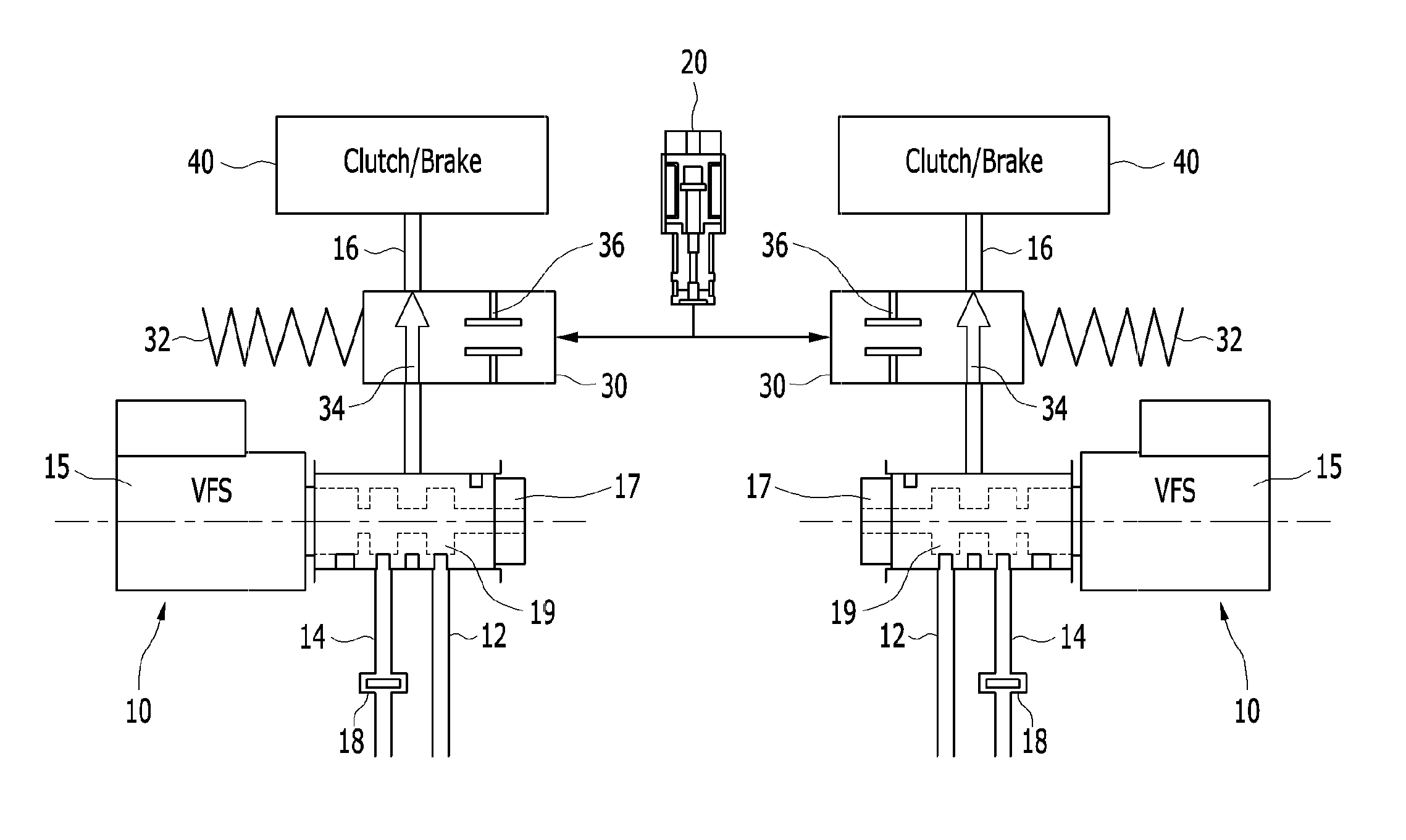
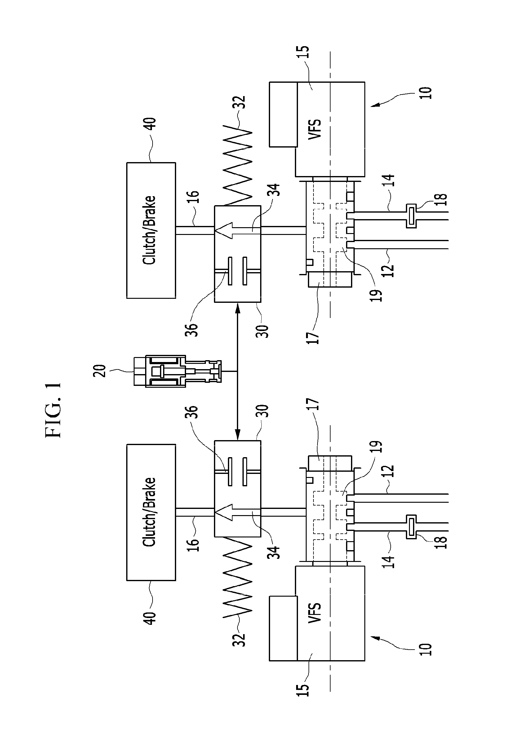
[0025]FIG. 1 is a schematic diagram showing a state in which a hydraulic circuit for an automatic transmission according to an exemplary embodiment of the present invention is not operated, and...


PUM


Abstract

A hydraulic circuit may include a proportional control solenoid valve controlling hydraulic pressure such that an operating hydraulic pressure required by the friction member is supplied to the friction member; a supply hydraulic path connecting the proportional control solenoid valve with the friction member, and adapted to supply hydraulic pressure controlled by the proportional control solenoid valve to the friction member; and a switch valve disposed in the supply hydraulic path so as to selectively open / close the supply hydraulic path.

Description

CROSS-REFERENCE TO RELATED APPLICATION[0001]The present application claims priority to Korean Patent Application No. 10-2013-0081047 filed on Jul. 10, 2013, the entire contents of which is incorporated herein for all purposes by this reference.BACKGROUND OF THE INVENTION[0002]1. Field of the Invention[0003]The present invention relates to a hydraulic circuit for an automatic transmission. More particularly, the present invention relates to a hydraulic circuit for an automatic transmission in which foreign materials having flowed into a circuit can be easily removed.[0004]2. Description of Related Art[0005]Generally, an automatic transmission provides convenient driving by achieving automatic shifting to a target shift speed as a consequence of the target shift speed being derived from a predetermined shifting pattern based on a vehicle speed and variation of a throttle opening, and then operational elements being controlled according to a hydraulic duty of the target shift speed. Th...

Claims


Application Information

Patent Timeline
Patent Type & Authority Patents(United States)
IPC IPC(8): F15B20/00F15B13/044F16D48/02
CPCF15B13/0442F16D48/02F15B2211/30515F15B2211/30525F15B2211/655F15B2211/85F16D2048/0278F16D2500/1085F16D2500/5118Y10T137/87193Y10T137/87209Y10T137/87217F16H61/0267F16H61/0276F16H2061/0279F16H61/00F16H61/4008F16H61/431
Inventor WI, TAEHWAN
Owner HYUNDAI MOTOR CO LTD
Why Eureka
Try Eureka