Eureka AIR delivers breakthrough ideas for toughest innovation challenges, trusted by R&D personnel around the world.

Post-hole digger with foot rests

a technology of footrests and digging tools, which is applied in the field of digging tools, can solve the problems of affecting soil fertility, tiring and inefficient use of conventional post-hole digging tools, and affecting soil fertility

Active Publication Date: 2016-11-29
HUDSON ANDREW JOHN +1
View PDF24 Cites 3 Cited by
  • Summary
  • Abstract
  • Description
  • Claims
  • Application Information

AI Technical Summary

Problems solved by technology

However, the typical tool does not allow the user to use his or her legs effectively in the process of driving the tool into the ground, and most people have more strength in their legs than in their arms.
Thus, using a conventional post-hole digger can be tiring and inefficient.
However, the posts extend horizontally far beyond the tool itself, which may interfere with the soil when one tries to dig particularly deep holes.
Moreover, the relatively long foot rests may increase the bending and tipping moments generated when pressure is applied, thus making the tool more difficult to use.
Additionally, when the Luck tool is in use, dirt and soils may become lodged in the hinges of its foot rests, potentially causing the hinges to jam.
If the foot rests open or the hinges jam open while the tool is in use, this could cause the foot rests to act like barbs on a hook, jamming the tool irretrievably in the hole.
While this may serve to rigidify the tool when it is driven, the top plate assembly and reinforcement bar prevent the tool from closing to remove soil when it is in place, and it may be inconvenient for a user to repeatedly attach and remove the top plate assembly while the tool is in use.
Beyond that inconvenience, it is very easy for the user to lose a detachable piece of a tool like the top plate assembly, which would render its advantages moot.

Method used


Image

  • Post-hole digger with foot rests
  • Post-hole digger with foot rests
  • Post-hole digger with foot rests

Examples


Embodiment Construction

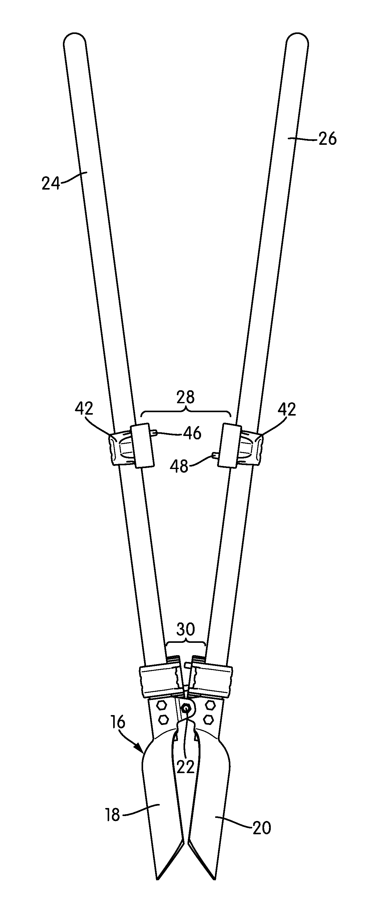
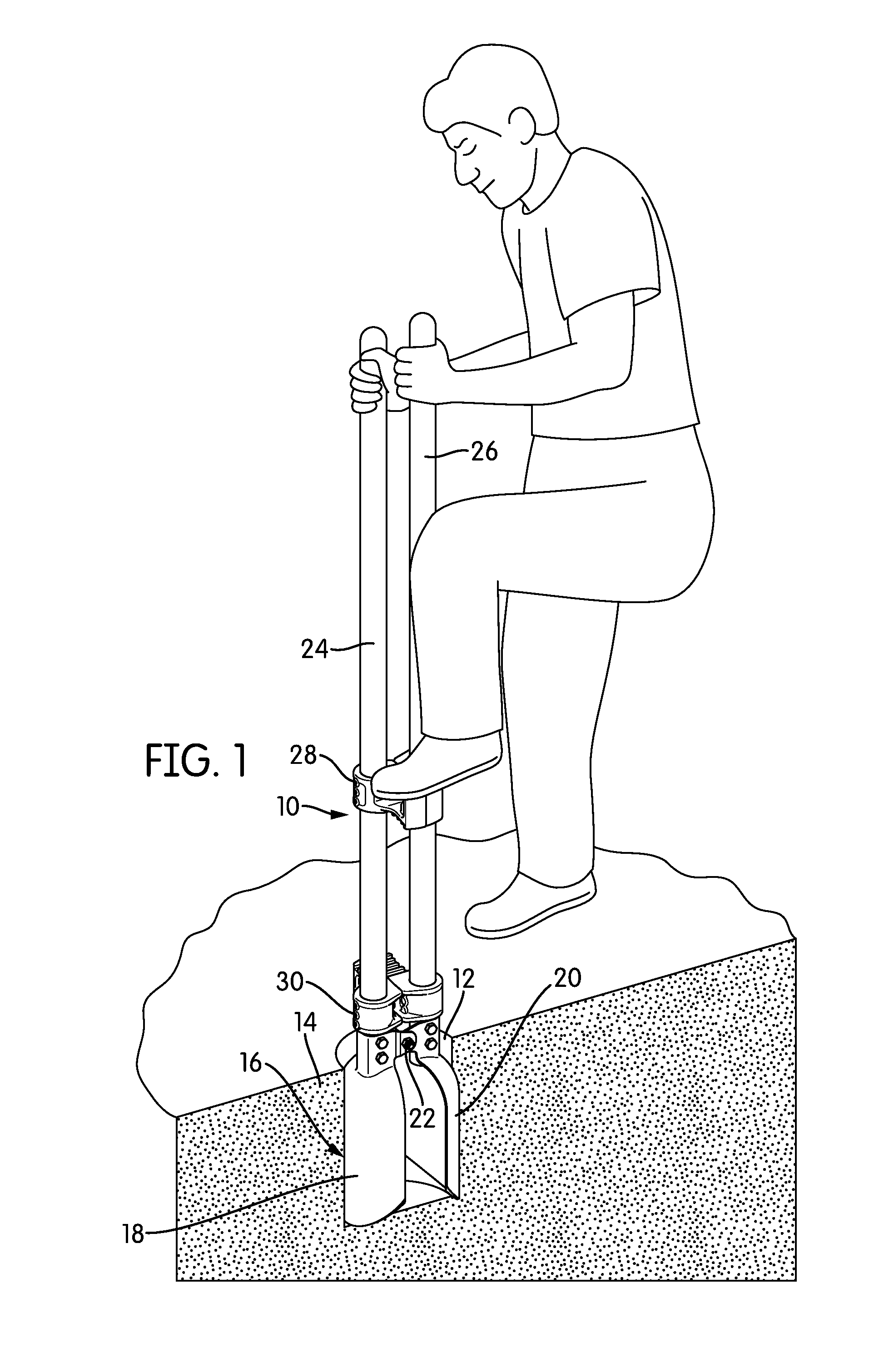
[0018]FIG. 1 is a perspective view of a post-hole digging tool, generally indicated at 10, according to one embodiment of the invention. The tool 10 is shown in FIG. 1 in use, digging a hole 12 in soil 14. The tool head 16 comprises two downwardly-extending, rounded digging blades 18, 20 that face one another and are connected together at a hinge 22, which pivots to allow the two digging blades 18, 20 to move closer together and farther apart. Each of the digging blades 18, 20 is connected to an individual shaft 24, 26 that, in the view of FIG. 1, extends vertically.

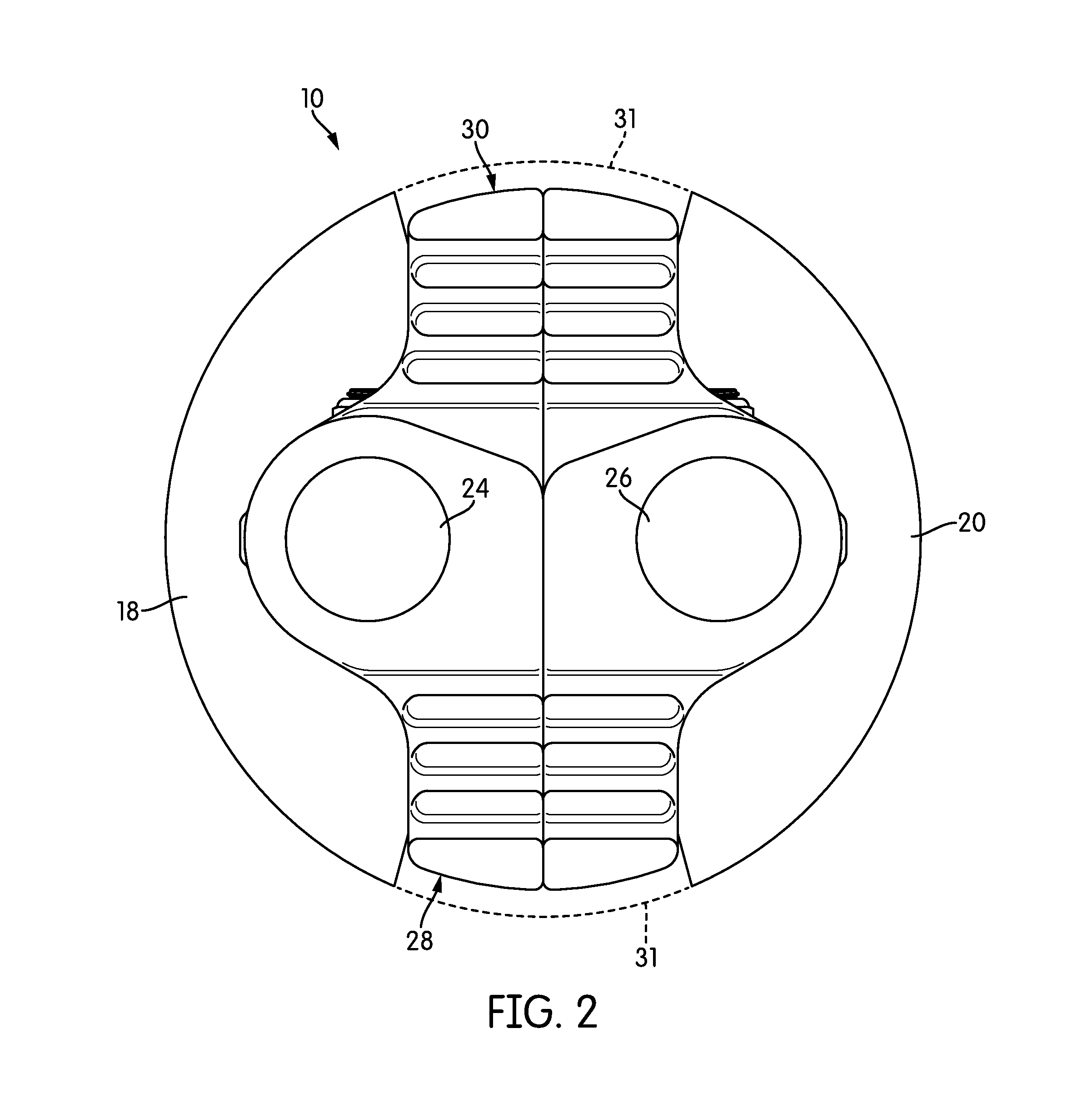
[0019]The tool 10 has a pair of foot rests 28, 30 spaced from one another along the length of the shafts 24, 26. Each foot rest 28, 30 extends in a different direction. The tool 10 may include any number of foot rests 28, 30 spaced from one another along the length of the shafts 24, 26. In fact, if a particularly deep hole 12 is to be dug, it may be helpful to have three or four foot rests 28, 30 present. The presence of...


PUM


Abstract

A foot rest for a post-hole digger and post-hole diggers using the foot rest are disclosed. The foot rest includes two portions, one attached to each shaft of the post-hole digger. The two portions have structure that allows them to engage one another when the two shafts of the post-hole digger are vertical. The foot rest does not extend beyond the bore diameter of the post-hole digger. Thus, in order to keep the user's feet on the relatively short foot rest, the contact surface of the foot rest may be angled. In some embodiments, the foot rest may be symmetrical, so that either side may be used as the upper surface. A post-hole digger including the foot rests typically includes at least two foot rests, spaced from one another and facing different directions along the shafts of the tool.

Description

BACKGROUND OF THE INVENTION[0001]1. Field of the Invention[0002]In general, the invention relates to digging tools, and more particularly, to post-hole digging tools with footrests.[0003]2. Description of Related Art[0004]A post-hole digger is a digging tool intended to dig deep, narrow holes for the placement of fence posts, sign posts, and other, similar structures. In a typical post-hole digger, the head of the tool includes two rounded digging blades that face one another and are connected to one another by a hinge. Each shovel head is connected to its own shaft. To use the device, the user drives the tool into the ground and then moves the handles to clamp down on some of the soil that the tool has sunk into before extracting the head, along with the soil, from the hole. The process is repeated until the hole is of sufficient size and depth.[0005]With a typical post-hole digger, the user uses his or her arms to drive the tool into the ground. However, the typical tool does not ...

Claims


Application Information

Patent Timeline
Patent Type & Authority Patents(United States)
IPC IPC(8): A01B1/00E21B11/00A01C5/02E02F3/02A01B1/02
CPCA01B1/024A01B1/02A01C5/02E02F3/02E21B11/005
Inventor HUDSON, ANDREW JOHNADAIR, CARALIN RIVA
Owner HUDSON ANDREW JOHN
Why Eureka
Eureka Blog
Learn More