Helicopter composite blade spar and method

a composite blade and spar technology, applied in the field of helicopter blades, can solve the problems of serious consequences for the safety and structural integrity of the composite blade, and the incorporation of unidirectional graphite and fiberglass plies in the blade spar, and achieve the effect of improving the spar construction

Active Publication Date: 2016-11-29
SIKORSKY AIRCRAFT CORP
View PDF22 Cites 13 Cited by
  • Summary
  • Abstract
  • Description
  • Claims
  • Application Information

AI Technical Summary

Problems solved by technology

This results in the incorporation of unidirectional graphite and fiberglass plies in the blade spars in the spanwise direction.
A crack initiation or manufacturing defect could cause a sudden disbond of the entire backwall scarf joint 104 leading to serious consequences for the safety and structural integrity of the composite blade.

Method used


Image

  • Helicopter composite blade spar and method
  • Helicopter composite blade spar and method
  • Helicopter composite blade spar and method

Examples


Embodiment Construction

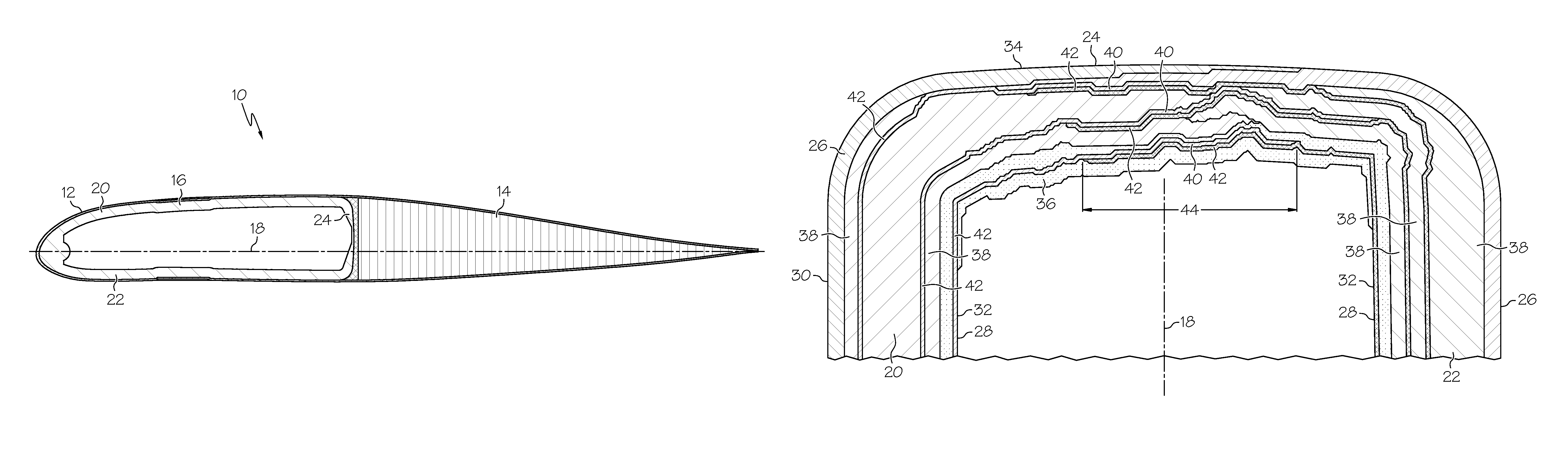
[0012]Shown in FIG. 1 is a cross-sectional view of a helicopter blade 10. The blade 10 includes a leading edge portion 12 and a trailing edge portion 14. One or more spars 16 are located along a chord 18 of the blade 10 and extend in a substantially spanwise direction along the blade 10. The spar 16 includes an upper airfoil portion 20, a lower airfoil portion 22 and a backwall 24 fabricated together as a composite laminate.

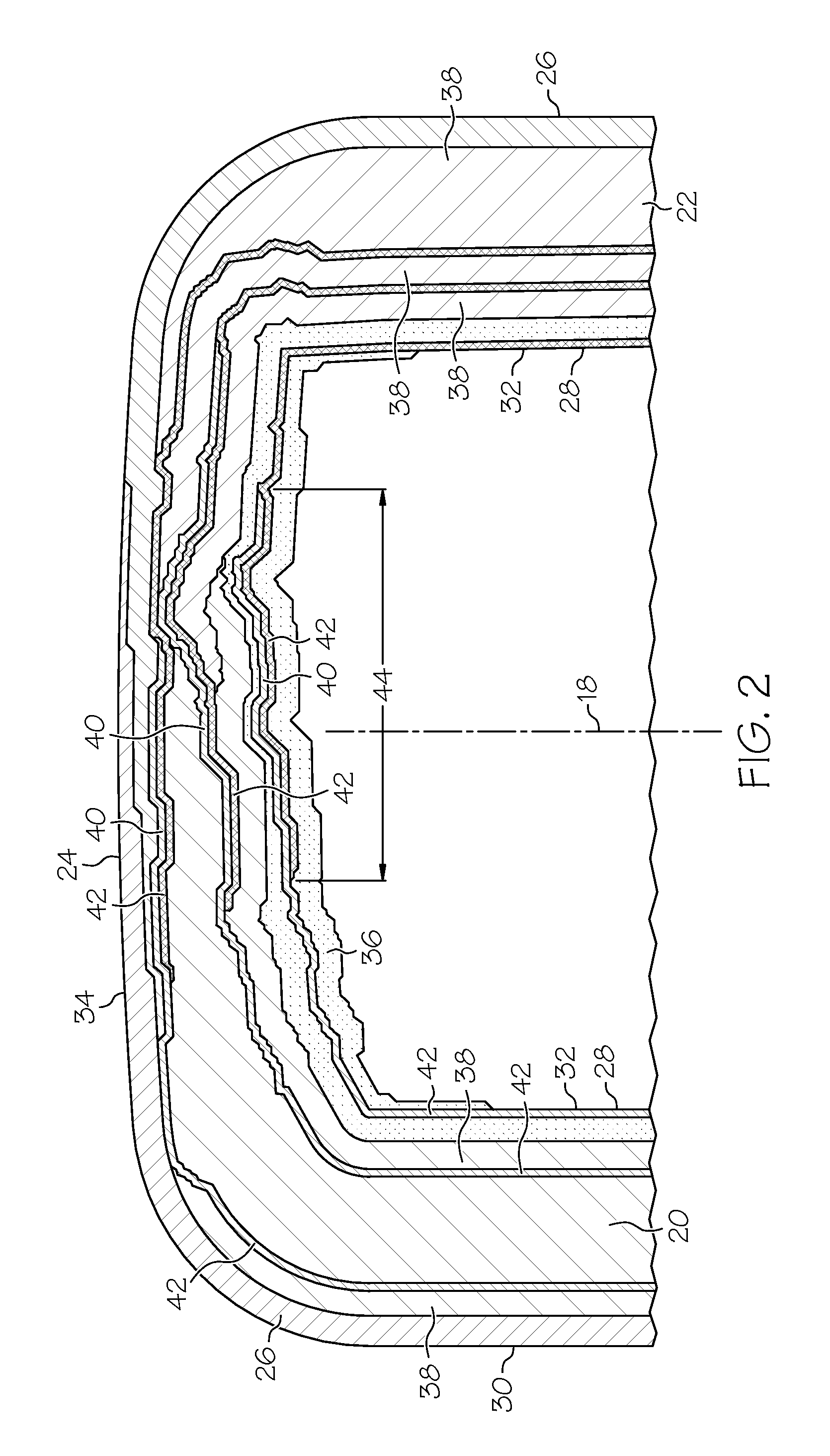
[0013]FIG. 2 is a rotated view of the backwall 24 of the spar 16. The upper airfoil portion 20 includes an outer layer 26 of a + / −45 degree graphite ply laminate and an inner layer 28 of a + / −45 degree graphite ply laminate. The outer layer 26 and the inner layer 28 define an outer surface 30 and inner surface 32, respectively. Likewise the lower airfoil portion 22 includes an outer layer 26 of a + / −45 degree graphite ply laminate and an inner layer 28 of a + / −45 degree graphite ply laminate defining an outer surface 30 and inner surface 32. The outer layers 26 o...


PUM

PropertyMeasurementUnit
thicknessaaaaaaaaaa
delamination lengthaaaaaaaaaa
overlap lengthaaaaaaaaaa

Abstract

A composite spar for a helicopter blade includes two or more layers of unidirectional laminate material. One or more upper plies of bi-directional laminate extend from an upper airfoil portion of the spar disposed between adjacent layers of the two or more layers of unidirectional laminate material. One or more lower plies of bi-directional laminate material extend from a lower airfoil portion of the spar disposed between adjacent layers of the two or more layers of unidirectional material. The upper plies and the lower plies overlap defining a crackstopper layer configured to prevent propagation of defects in the spar.

Description

CROSS-REFERENCES TO RELATED APPLICATION[0001]This patent application claims priority to U.S. Provisional Patent Application Ser. No. 61 / 375,165 filed Aug. 19, 2010, which is incorporated herein by reference in its entirety.BACKGROUND OF THE INVENTION[0002]The subject matter disclosed herein relates to helicopter blades. More specifically, the subject disclosure relates to construction and methodology of construction of a composite spar for helicopter blades.[0003]Typical helicopter composite blade spars have spanwise and chordwise stiffness and structural requirements. The upper and lower airfoils of the blade are generally the most effective in generating the high bending and axial stiffnesses required for spanwise bending and centrifugal loading conditions. This results in the incorporation of unidirectional graphite and fiberglass plies in the blade spars in the spanwise direction. The total thickness and combination are a function of strength and dynamic requirements. Additional...

Claims


Application Information

Patent Timeline
Patent Type & Authority Patents(United States)
IPC IPC(8): B64C27/473B29C70/30B29C70/08B29L31/08
CPCB64C27/473B29C70/083B29C70/30B29L2031/082B64C2027/4736Y10T156/10
Inventor BYRNES, FRANCIS EDWARDFEHRMAN, JACOB A.
Owner SIKORSKY AIRCRAFT CORP
Why Eureka
Try Eureka