Gas pressurized packing system for control valves

a technology of pressure packing and control valve, which is applied in the direction of valve housing, spindle sealing, operating means/releasing devices of valves, etc., can solve the problems of increasing the friction experienced by the operating member, increasing the packing stress, and unsatisfactory effects on the operation and performance of the control valve, so as to inhibit fugitive emissions

Active Publication Date: 2016-12-27
FISHER CONTROLS INT LLC
View PDF20 Cites 16 Cited by
  • Summary
  • Abstract
  • Description
  • Claims
  • Application Information

AI Technical Summary

Benefits of technology

[0011]In one preferred form, the first plurality of packing rings has a V-shaped cross-section pointing in a downward direction, and the second plurality of packing rings has a V-shaped cross-section pointing in an upward direction.

Problems solved by technology

However, these solutions can have undesirable effects on the operation and performance of the control valve.
For instance, increasing the packing stress tends to increase the friction experienced by the operating member.
The increased friction impedes movement of the operating member, which, in turn, can make it difficult to monitor and control the position of the control member.
Higher levels of friction also may necessitate a larger actuator, which can increase the operating and manufacturing costs associated with the control valve.
Furthermore, a metal bellows seal tends to be expensive to install, may require regular field maintenance and / or replacement, and / or may limit the travel distance of the operating member.

Method used


Image

  • Gas pressurized packing system for control valves
  • Gas pressurized packing system for control valves
  • Gas pressurized packing system for control valves

Examples


Embodiment Construction

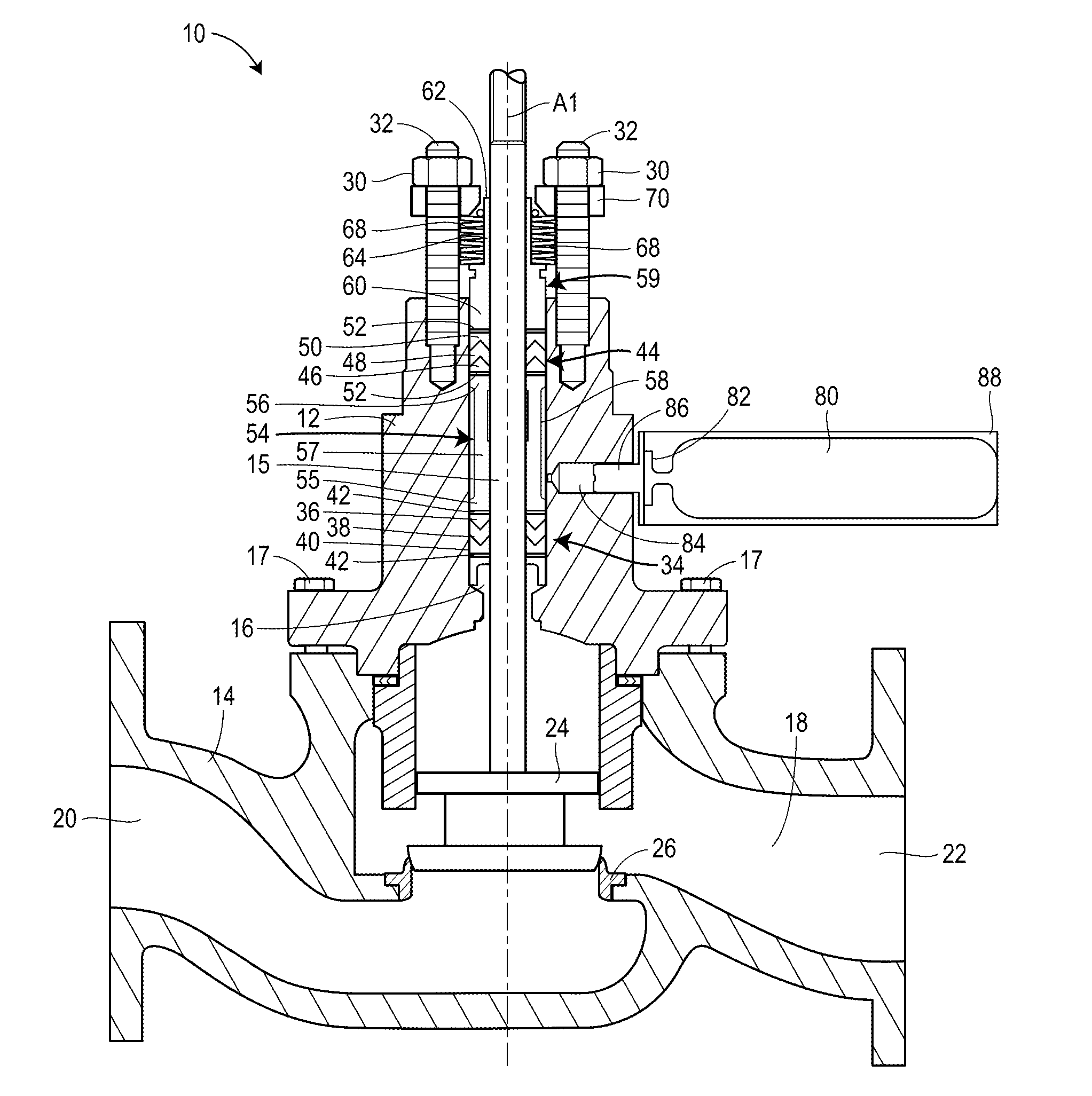
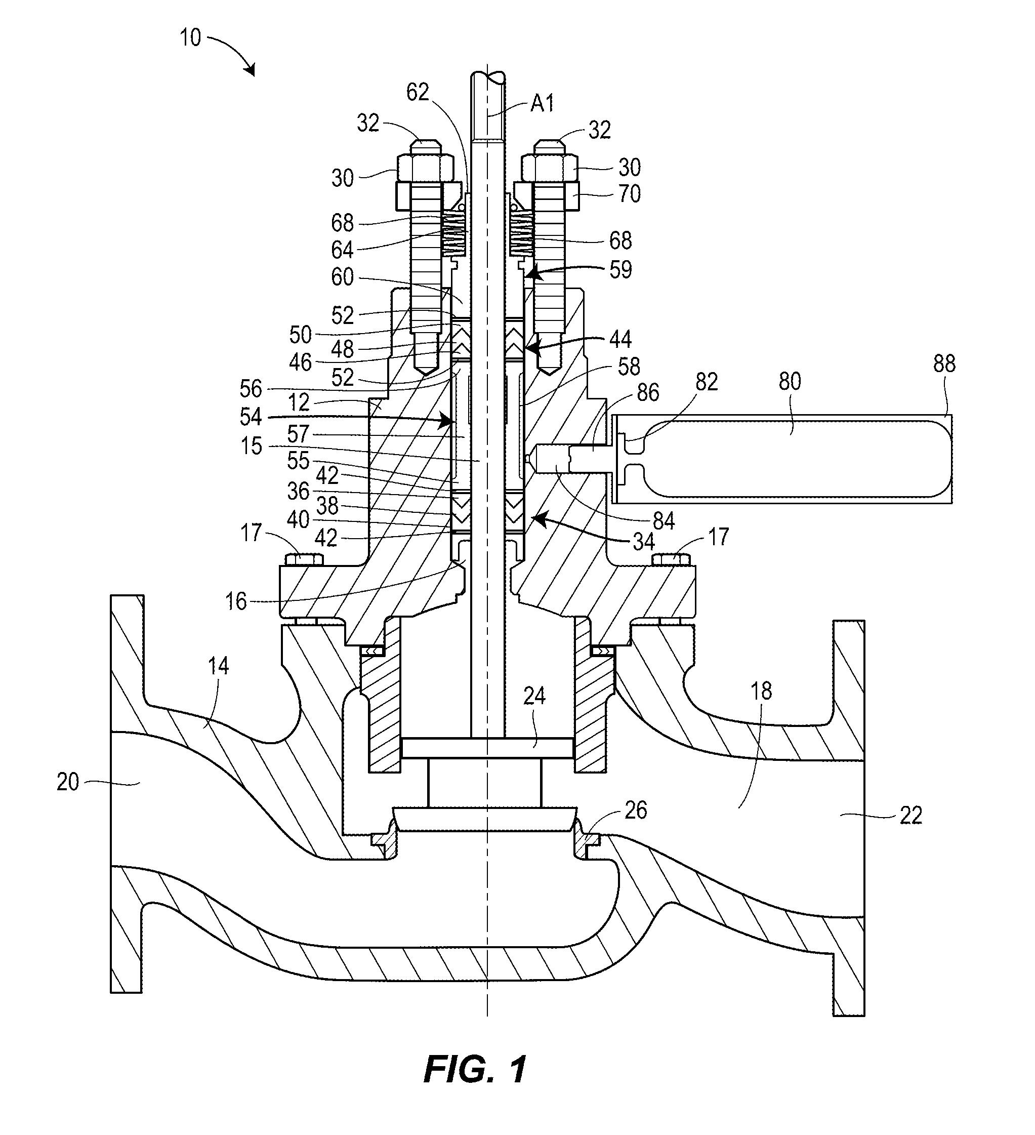
[0029]The principles of the present disclosure are applicable to various types of control valves, such as sliding stem control valves and rotary shaft control valves, as well as, various packing arrangements, such as jam-style or live-loaded, and various packing materials, such as polytetrafluoroethylene (PTFE) and graphite. FIG. 1 illustrates, for instance, a control valve 10 of the sliding stem type, having a live-loaded packing arrangement and PTFE packing rings, which incorporates a gas pressurized packing system in accordance with principles of the present disclosure.

[0030]The illustrated portion of the control valve 10 includes a bonnet 12 mounted on a valve body 14 and an operating member, such as sliding stem 15, that extends through a bore 16 formed in the bonnet 12. Fasteners 17 may be used to removably secure the bonnet 12 to the valve body 14. A flow passage 18 extends through the valve body 14 between an inlet 20 and an outlet 22 and provides a path for a process liquid...


PUM


Abstract

A gas pressurized packing system for use in a control valve may include a first packing member, a second packing member and a pressurized gas supply. The first and second packing members may be arranged about, respectively, lower and upper portions of an operating member that extends through a bore in the control valve. The pressurized gas supply may be configured to pressurize a portion of the bore arranged between the first and second packing members. The gas pressurized packing system may be implemented in a low fugitive emission control valve and a low fugitive emission control valve system.

Description

FIELD OF DISCLOSURE[0001]The present application relates generally to control valves, and, more particularly, to a packing assembly for use in a control valve to limit fugitive emissions.BACKGROUND OF THE DISCLOSURE[0002]Control valves are used in a wide variety of applications including process plants such as refineries, chemical plants, and paper plants, among many others. Control valves typically employ a control member such as a valve plug, a valve disc or other suitable control member, to manipulate a process fluid or gas flowing through a pipeline, such as a steam, water, natural gas, oil or a chemical compound. The control member is typically moved by an operating member, such as a sliding valve stem or a rotary shaft, that extends through a bore in the valve body. To prevent leakage or fugitive emissions of the process fluid or gas around the operating member, packing material is typically arranged about the operating member in the bore.[0003]Many process applications, such ...

Claims


Application Information

Patent Timeline
Patent Type & Authority Patents(United States)
IPC IPC(8): F16K41/02F16K41/00F16K31/44F16K27/02F16K1/36
CPCF16K41/02F16K1/36F16K27/02F16K31/445F16K41/003F16K1/00F16K5/0694F16K41/04F16J15/18
Inventor MCCARTY, MICHAEL WILDIE
Owner FISHER CONTROLS INT LLC
Why Eureka
Try Eureka