Check patentability & draft patents in minutes with Patsnap Eureka AI!

Delay locked loop and associated control method

Active Publication Date: 2017-01-24
XUESHAN TECH INC
View PDF5 Cites 0 Cited by
  • Summary
  • Abstract
  • Description
  • Claims
  • Application Information

AI Technical Summary

Benefits of technology

The patent aims to prevent disturbances caused by changes in a reference clock signal, which can affect the performance of amultiplying delay locked loop (MDLL). The invention helps to stabilize the reference clock signal, resulting in improved performance of the MDLL.

Problems solved by technology

However, the MDLL 100 suffers from certain issues, and needs to be carefully designed.
Further, with a small design mistake, the jitter in the reference clock signal rclk may lead to disturbances in the MDLL 100 to incur wrongful results.

Method used


Image

  • Delay locked loop and associated control method
  • Delay locked loop and associated control method
  • Delay locked loop and associated control method

Examples


Embodiment Construction

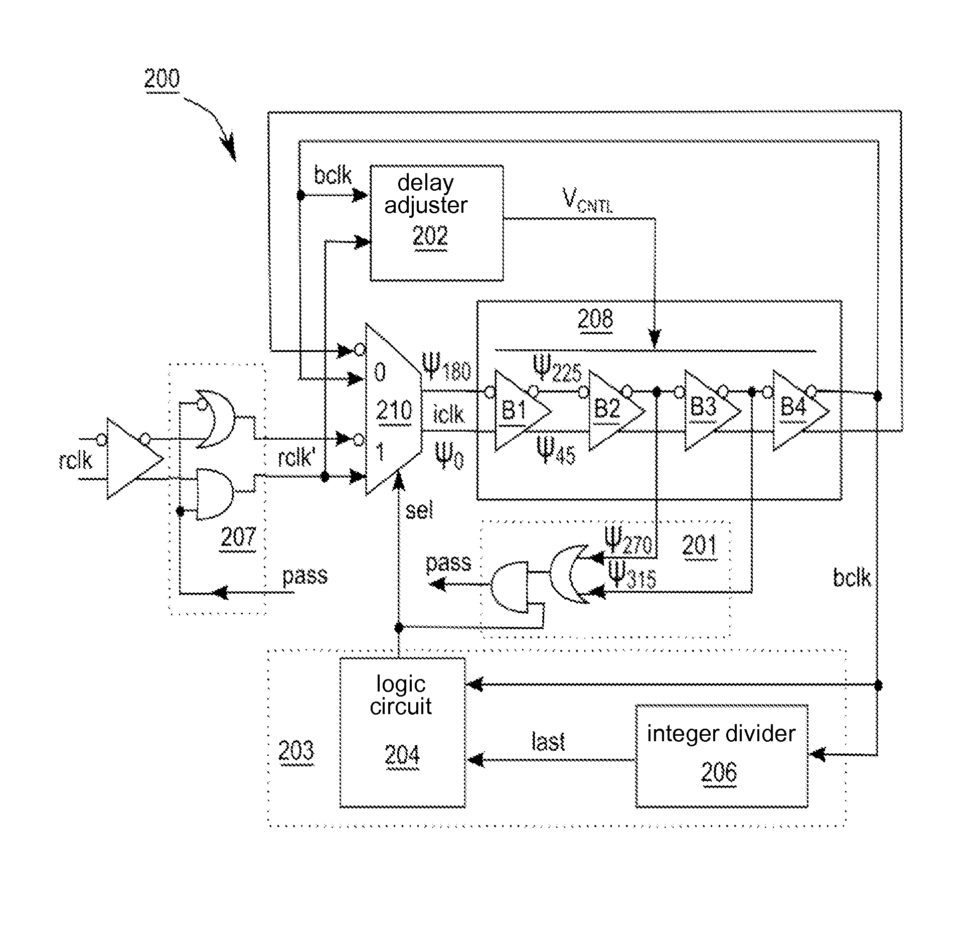
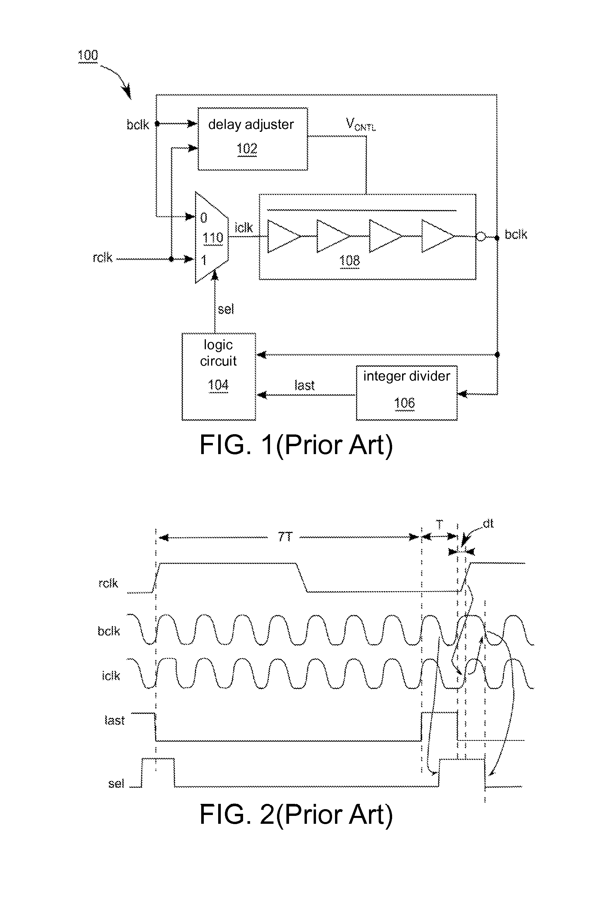
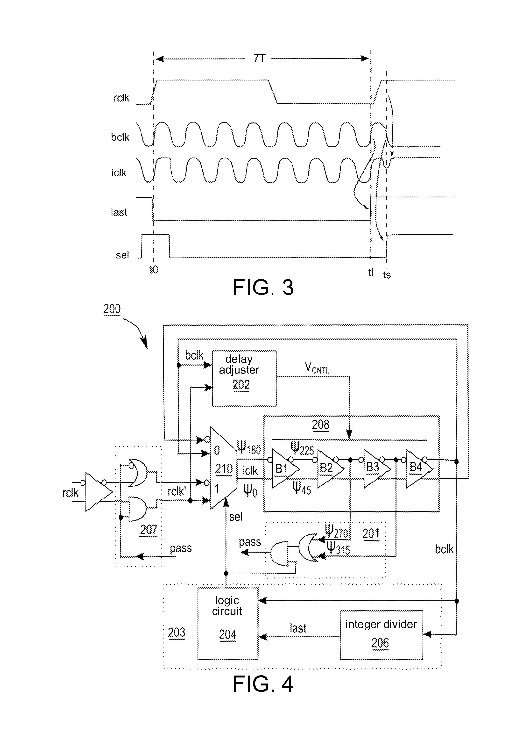
[0020]FIG. 3 shows another timing diagram of signals in the MDLL 100 for explaining possible issues in the MDLL 100 when the frequency of the reference clock signal rclk jitters drastically.

[0021]As shown in FIG. 3, at a time point t0, the phase is substantially locked as a rising edge of the reference clock signal rclk and a rising edge of the output signal bclk appear approximately at the same time. However, due to the jitter in the reference clock signal rclk, a next rising edge of the reference clock signal rclk appears ahead of time, and is even earlier than a time point is at which the pulse of the selection signal sel starts to appear.

[0022]In FIG. 3, just as the rising edge of the last signal last appears (at a time point tl), the multiplexer 110 still utilizes the output signal bclk as the input signal iclk, and so the input signal iclk has substantially the same waveform as the output signal bclk. At the time point ts, being triggered by the falling edge of the output sign...


PUM


Abstract

A control method for a delay locked loop includes: delaying an input signal to generate an internal signal; delaying the internal signal to generate an output signal; and selectively providing a reference clock signal or the output signal as the input signal according to the output signal and the internal signal.

Description

[0001]This application claims the benefit of Taiwan application Serial No. 104125591, filed Aug. 6, 2015, the subject matter of which is incorporated herein by reference.BACKGROUND OF THE INVENTION[0002]Field of the Invention[0003]The invention relates in general to a delay locked loop, and more particularly to a multiplying delay locked loop.[0004]Description of the Related Art[0005]A timing device is commonly applied in electronic devices and systems to generate a clock and to allow various elements to operate synchronously. A multiplying delay locked loop (MDLL) is one of the above conventional timing device, as exemplified by an MDLL 100 in FIG. 1. FIG. 2 shows a timing diagram of signals in the MDLL 100. In the MDLL 100, every rising edge of a reference clock signal rclk enters a delay line via a multiplexer 110. After a rising edge of the reference clock signal rclk enters the delay line 108 via the multiplexer 110, a selection signal sel switches to select an output signal bc...

Claims


Application Information

Patent Timeline
IPC IPC(8): H03L7/06H03L7/08H03K5/14H03K5/00
CPCH03L7/0805H03K5/14H03K2005/00019H03L7/0995H03L7/07
Inventor WENG, MENG-TSELIU, HSIAN-FENGLEE, CHIEH-WEN
Owner XUESHAN TECH INC
Features
  • R&D
  • Intellectual Property
  • Life Sciences
  • Materials
  • Tech Scout
  • Unparalleled Data Quality
  • Higher Quality Content
  • 60% Fewer Hallucinations
Learn More