Twin-engined rotorcraft having a fuel supply installation for a power plant auxiliary power unit (APU)

a technology of auxiliary power units and rotorcrafts, which is applied in the direction of vehicle, turbine/propulsion fuel control, turbine/propulsion fuel delivery, etc., can solve the problems of fuel tanks possibly running out, difficulty in such an approach, and nothing states nor suggests using an auxiliary power unit in addition to the two main engines, so as to simplify the installation. the effect of the installation

Active Publication Date: 2017-02-28
EUROCOPTER
View PDF14 Cites 8 Cited by
  • Summary
  • Abstract
  • Description
  • Claims
  • Application Information

AI Technical Summary

Benefits of technology

[0051]Consequently, having the auxiliary power unit mechanically engaged with the drive train for driving the rotor(s) of the rotorcraft is viable, while also complying with safe flying conditions in the event of one of the main tanks running out of fuel, and this is achieved without making the fuel supply installation of the power plant of the rotorcraft more complex in a manner that is economically unacceptable.
[0054]The architecture of the auxiliary supply assembly is simplified by not having a fuel tank specific to the auxiliary power unit, while still being suitable for maintaining a supply of fuel to the auxiliary power unit in the event of fuel running out in one of the main tanks, and while still complying with safe flying conditions for the rotorcraft, and possibly indeed optimizing such safe flying conditions in the event of one of the main engines failing by supplying additional mechanical power from the auxiliary power unit, in particular for assisting in driving the rotor(s) of the rotorcraft.
[0057]Each of said two auxiliary channels may advantageously be provided with a check valve preventing fluid from passing from either one of the main tanks to the other. Such arrangements and the organization of the auxiliary duct make it possible, using simple structural techniques, reliably to prevent fluid passing from one of the main tanks to the other via the auxiliary fluid flow circuit. Such provisions are useful in particular in the event of one of the main fuel tanks running out of fuel, so as to prevent air passing from the empty main tank to the other main tank and / or to the auxiliary power unit.

Problems solved by technology

There arises a problem of fuel tanks possibly running out of fuel, e.g. as a result of fuel leaking from a faulty tank or as a result of the main engine associated with the tank consuming all of the fuel that was initially contained in that tank.
Nevertheless, in that document, nothing states nor suggests using an auxiliary power unit in addition to the two main engines for driving a main rotor.
Nevertheless, under such circumstances, the main tanks do not have feeders.
It is found in practice that such prejudices go against using the auxiliary power unit for providing any participation in the driving of the rotor(s) of a category A multi-engined rotorcraft because of the extra complexity that arises in the architecture for feeding fuel to the power plant.
The difficulty of such an approach is to be seen in particular when said multi-engined rotorcraft is a twin-engined rotorcraft, i.e. a rotorcraft having a power plant with two of said main fuel-burning engines each of dimensions suitable for individually driving the rotor(s) of the rotorcraft in flight in the event of a failure of one of the main engines.
In such a context, in the event of one of the main engines failing, only one main engine is available for providing the mechanical power needed to keep the rotorcraft in flight under safe flying conditions, since the auxiliary power unit is incapable on its own of providing the drive required by the rotor(s) of the rotorcraft.

Method used


Image

  • Twin-engined rotorcraft having a fuel supply installation for a power plant auxiliary power unit (APU)
  • Twin-engined rotorcraft having a fuel supply installation for a power plant auxiliary power unit (APU)
  • Twin-engined rotorcraft having a fuel supply installation for a power plant auxiliary power unit (APU)

Examples


Embodiment Construction

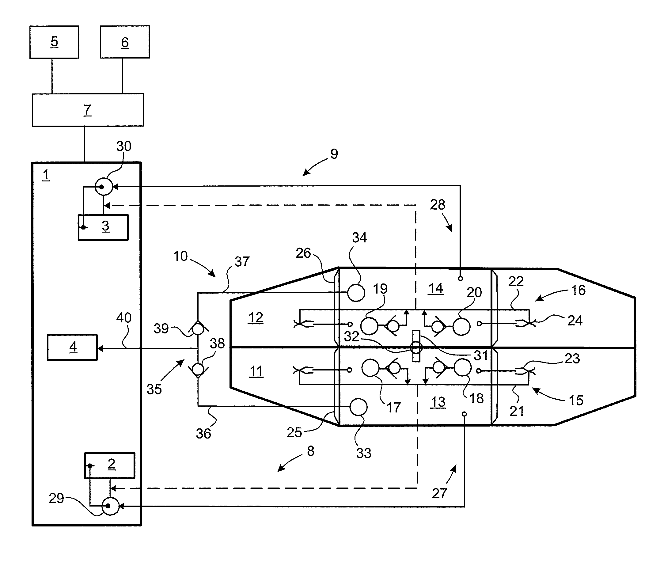
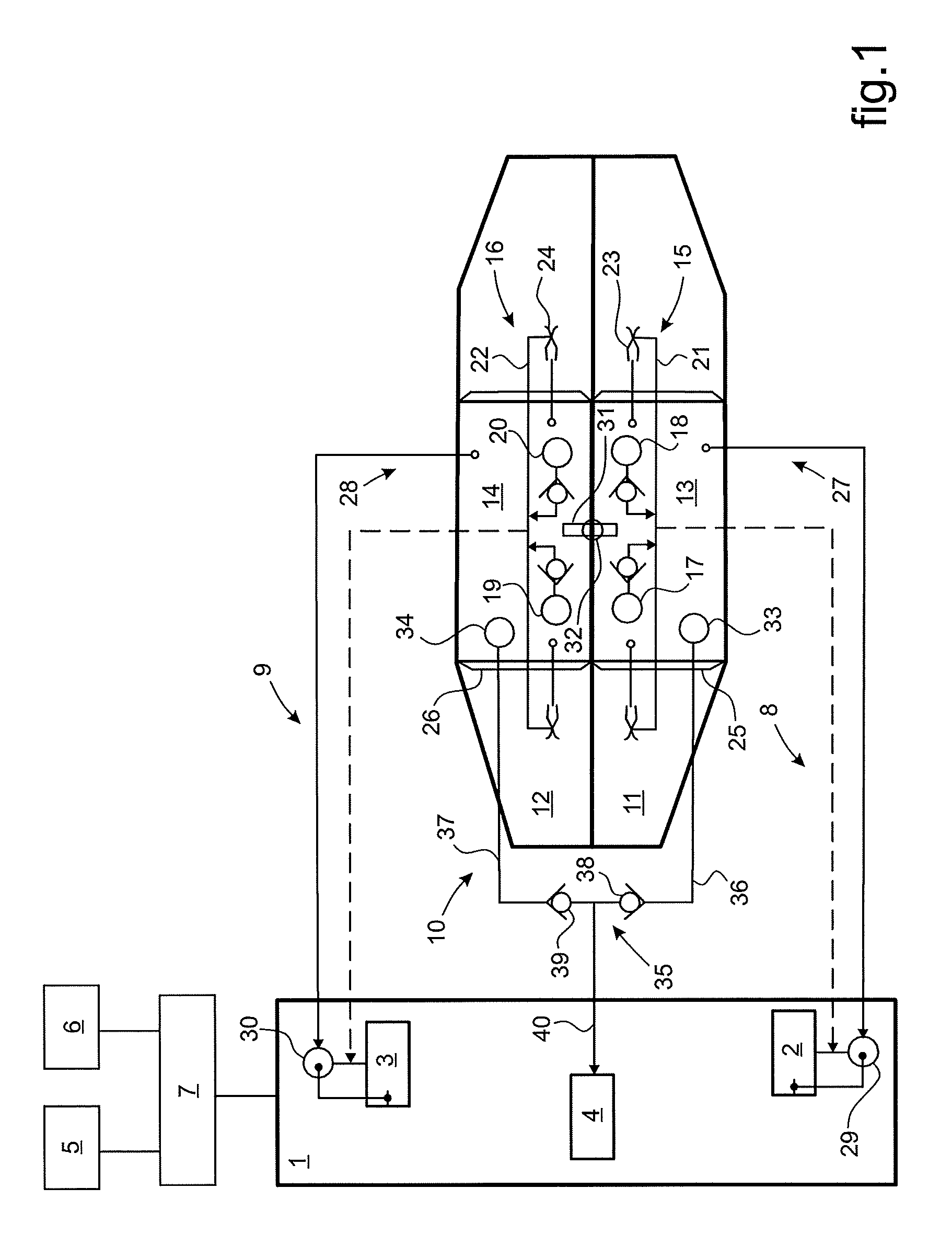
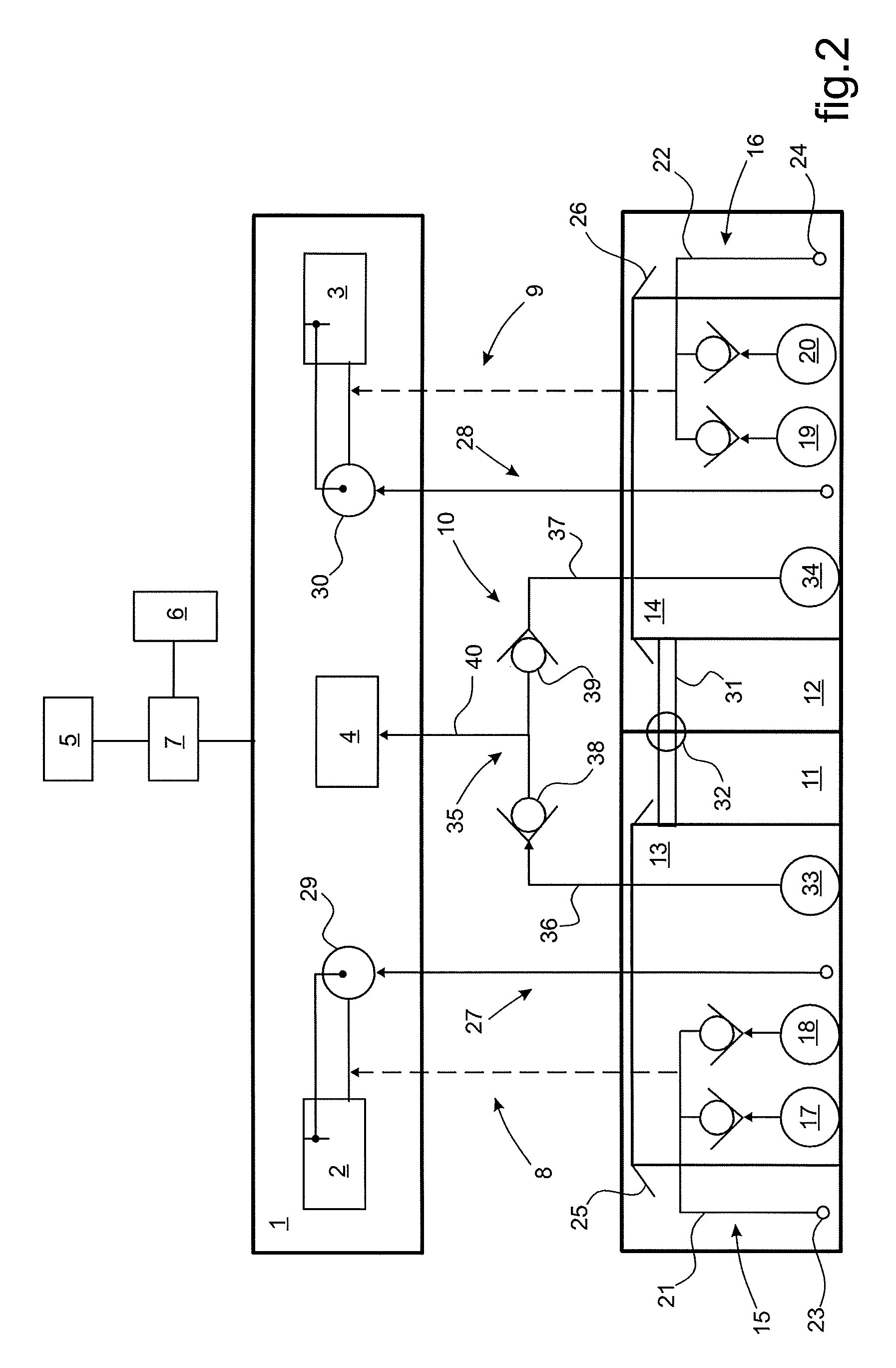
[0069]In FIGS. 1 and 2, a twin-engined rotorcraft has a power plant 1 providing the rotorcraft with the mechanical power required for its operation. The power plant 1 has main fuel-burning engines 2 and 3 and an auxiliary fuel-burning power unit 4 that are supplied with fuel by means of a fuel supply installation for the power plant 1.

[0070]In the context of a twin-engined rotorcraft, the main engines 2 and 3 are two in number, and typically each of them is designed to be capable on its own of supplying the mechanical power needed for driving at least one rotor 5 of the rotorcraft in flight.

[0071]Said rotor 5 is in particular a rotor that is commonly referred to as the “main” rotor that typically provides the rotorcraft at least with lift and possibly also with propulsion and / or guidance in flight in the specific example of a helicopter. Said rotor 5 is potentially also associated with at least one auxiliary rotor providing the rotorcraft with guidance in yaw and possibly also with ...


PUM


Abstract

A twin-engined rotorcraft having an installation for feeding fuel to fuel-burning engines of a power plant of the rotorcraft, the engines including main engines suitable individually for driving at least one rotor of the rotorcraft while in flight, and an auxiliary power unit mechanically connected to the rotor while nevertheless being unsuitable on its own for driving it in flight. The auxiliary power unit is fed with fuel by auxiliary pumps drawing fuel from each of main fuel tanks from which the main engines are respectively fed with fuel.

Description

CROSS REFERENCE TO RELATED APPLICATION[0001]This application claims priority to French patent application No. FR 14 01226 filed on May 28, 2014, the disclosure of which is incorporated in its entirety by reference herein.BACKGROUND OF THE INVENTION[0002](1) Field of the Invention[0003]The present invention lies in the field of rotorcraft and it relates more particularly to ways of supplying fuel to a power plant of the rotorcraft.[0004]The present invention relates to an architecture for supplying fuel to a multi-engined power plant of a rotorcraft that supplies mechanical power at least for driving at least one rotor of the rotorcraft.[0005](2) Description of Related Art[0006]Rotorcraft are rotary wing aircraft having one or more rotors providing the rotorcraft at least with lift, and possibly also with propulsion and / or guidance in flight. Rotorcraft are also provided with various auxiliary members that consume mechanical power, such as compressors, electricity generators, and / or ...

Claims


Application Information

Patent Timeline
Patent Type & Authority Patents(United States)
IPC IPC(8): B64D37/20F02C7/236B64D41/00F02C9/42B64D37/08B64C27/12
CPCB64D37/20B64C27/12B64D37/08B64D41/00F02C7/236F02C9/42Y02T50/671Y02T50/40Y02T50/60B64C27/04B64D37/00
Inventor BORNES, SYLVAIN
Owner EUROCOPTER
Why Eureka
Try Eureka