
Machine to Build Structures

a technology of building structures and machines, applied in the field of machines to build structures, can solve the problems of product unavailable to a majority market, enormous amounts of human labor, skyrocketing total cost, etc., and achieve the effects of facilitating adaptation to use, and enhancing the quality and speed of traditional construction and manufacturing methods

Inactive Publication Date: 2017-05-11
BOLIVAR EDGAR
View PDF0 Cites 13 Cited by
  • Summary
  • Abstract
  • Description
  • Claims
  • Application Information

AI Technical Summary

Benefits of technology

The purpose of this invention is to automate the construction process, replacing human labor with machines. It aims to reduce wasted materials, speed up construction and manufacturing practices, and provide a structure building machine that can deposit and remove material using various methods. The machine can easily incorporate programs like milling or cutting, and can coordinate its movements to create the desired outcome.

Problems solved by technology

Traditional construction methods involves enormous amounts of human labor, skyrocketing total costs, making the product unavailable to a majority market.
Wasted materials are common and to be expected during construction, 15% of materials that went into production are wasted on average, increasing costs unnecessarily.
Weather delays, material damage due exposure to weather.
Often dangerous situations such as high altitude brick laying.
Prefab, even 3d printed prefab commonly requires crane and heavy truck access, especially for multi-story, not to mention the high cost related to the transport and installation of these structures, plus even with current advances in technology and construction, human labor is still needed in order to finish out the structure and prepare it for dwellers.
Construction sites are normally very dangerous places and construction work is recognized as an accident prone occupation.
Currently, the size of an object 3d printed is limited to the size of the printer.
Printing times tend to be slow, and therefore limiting the production capabilities for the machines.
This reference is deficient in that the machine described requires a raw material that is not readily available and that it requires work and energy to prepare, to get it into the form of a brick.
Then that means that overall a house constructed of brick will be more expensive to build than a house made out of concrete or clay just taken right off the ground, the reference is also deficient in that the machine described is only capable of building the walls, which means that still quite a lot of human labor has to be involved in the development of structures while using this method for the construction of the walls.
This reference is deficient in that the method of building the wall itself requires human labor.
This reference is deficient in that robotic arms are normally mounted stationary or with very restricted mobility, therefore limiting the amount of work that an arm would have because of its reach is limited to the size of the arm.
This reference is deficient in that a lift machine is required to have mobility for this application, maneuverability is required in all directions and is also necessary for the lift to work autonomously, knowing when to perform the operations and movements needed and to coordinate with the robot arms as they work is imperative.
This reference is deficient in that an omnidirectional vehicle has to have means to provide the extra height, the robotic arms would need in order to continue building as the structure rises.
This reference is also deficient in that the movement of the machine cannot be controlled by remote or a human, so the motors which turn the wheels of the driving module have to be completely autonomous, know its position relative to the build area, know obstacles and coordinate within the process with other machines working around, with or near it.
This reference is deficient in that the vehicle would have to possess a form of way to change the center of gravity of the vehicle when working with the lift completely extended, even while the vehicle moves and especially when working on an incline.
The robotic arms themselves can perform the work without any problem at almost any angle, but the platform is liable to tip, as the weight of the arms, the lift's center of gravity, the weight of the tools, the weight of the material and the inertia that the machine will have anytime the platform is moving, all these are factors that will have limitations for the use of this machine.
This reference is deficient in that the end effectors that the process requires, are utilized by the machine around the product being built from scratch, normally the product is able to be delivered to where the end effector is, and from there the robot can take over the handling of the tool.
The problem in this case is that the end effector needs to be manipulated over a very large area, and operated even from within the structure itself while being built at any point of its production.

Method used


Image

  • Machine to Build Structures
  • Machine to Build Structures
  • Machine to Build Structures

Examples


Embodiment Construction

1. Definitions

[0045]Extrusion is a process used to create objects of a fixed cross-sectional profile. A material is pushed through a die of the desired cross-section.

[0046]In robotics, an end effector is the device at the end of a robotic arm, designed to interact with the environment. The exact nature of this device depends on the application of the robot.

2. Best Mode of the Invention

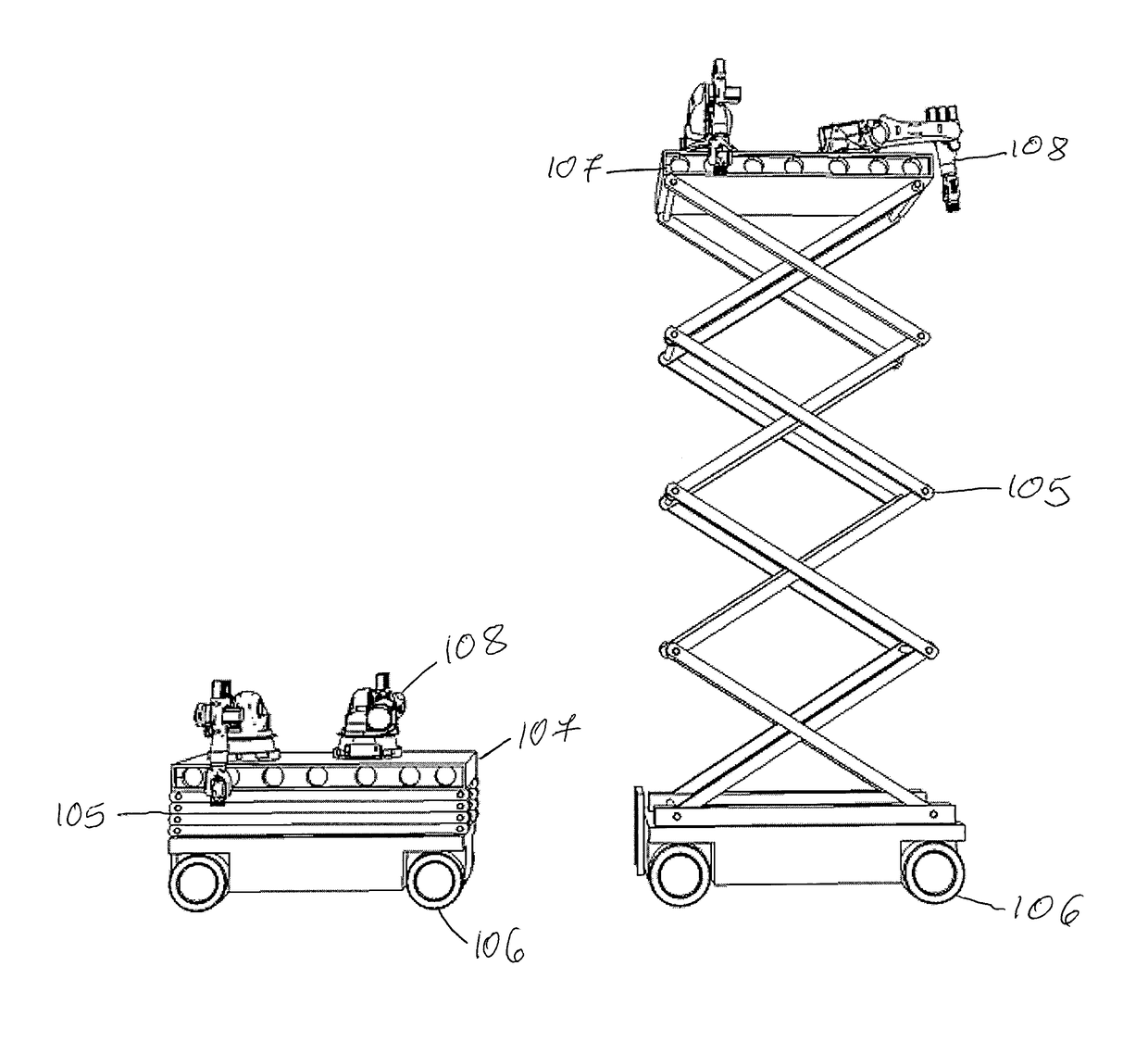
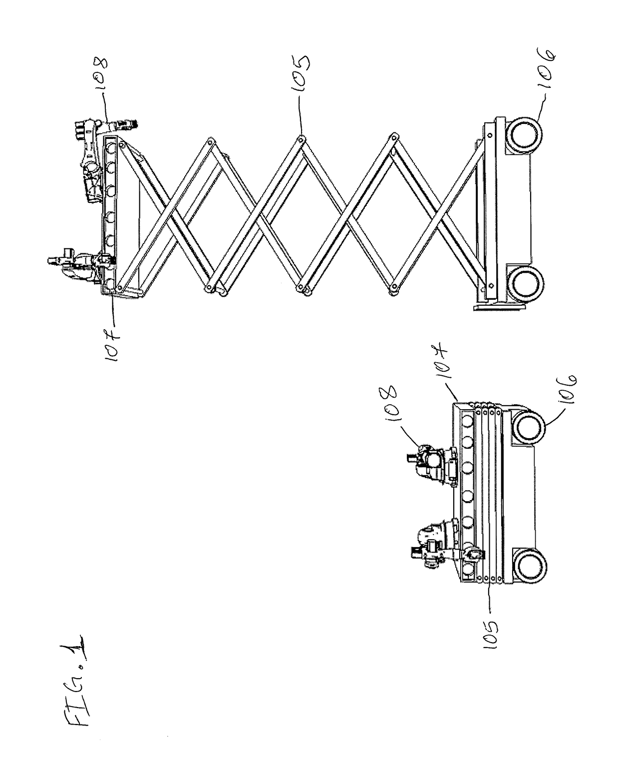
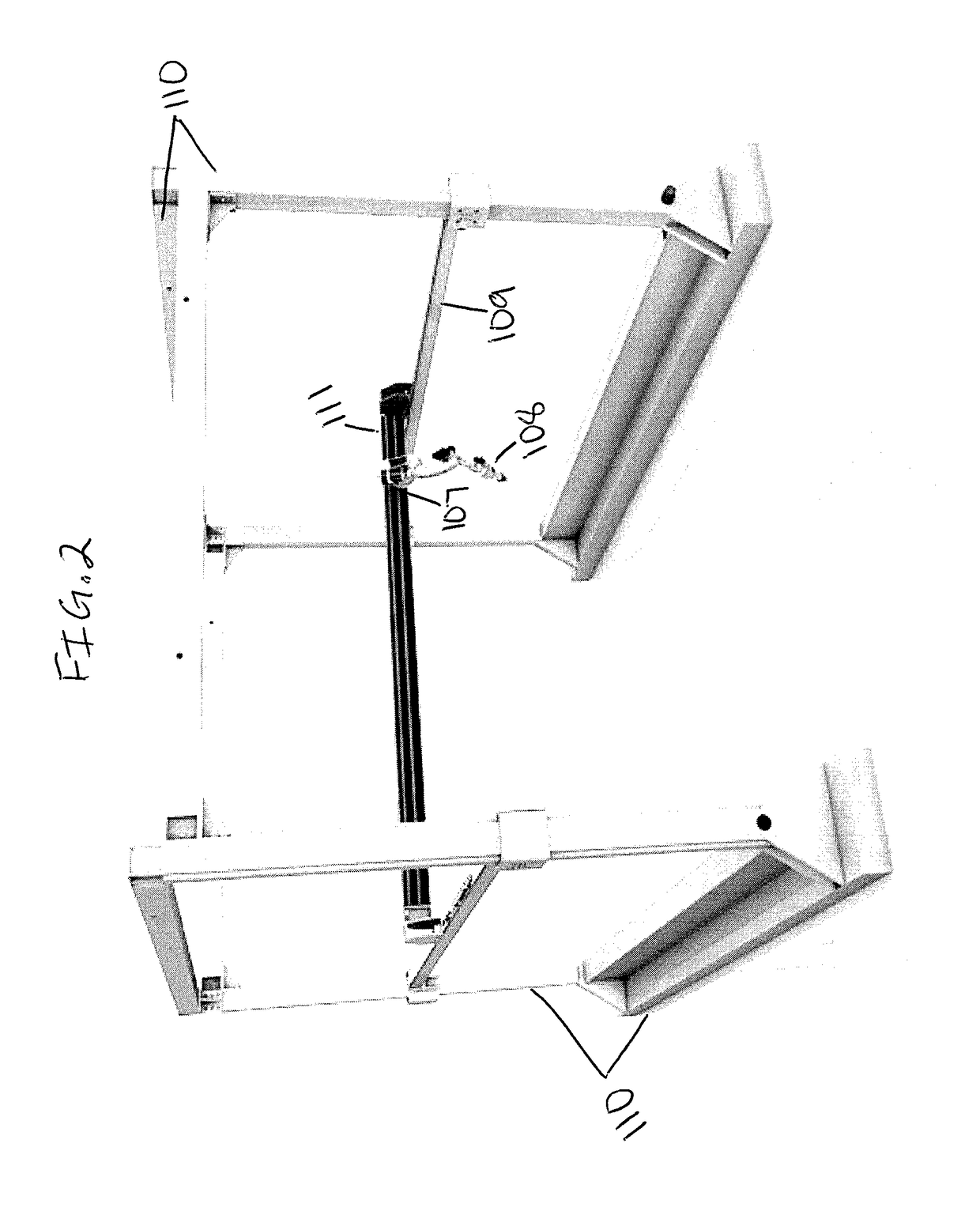
[0047]FIG. 1 shows a side view of the best mode contemplated by the inventor of the machine to build structures according to the concepts of the present invention. Its design incorporates omni-directional wheels (106) which will allow movement to the platform in any direction. Uses one or more robotic arms (108) as replacement for current conventional extruders to expand on the flexibility that the machine could possess, since essentially almost any tool could be incorporated to do a specific job now that we have an infinite and free range of movements, not limited to any space and giving us the opport...


PUM

PropertyMeasurementUnit
sharp anglesaaaaaaaaaa
construction timeaaaaaaaaaa
flexibilityaaaaaaaaaa

Abstract

Disclosed is a machine meant to build structures capable of moving over a surface, having unlimited range, for the purpose of doing tasks involved in the manufacturing of a structure or building: from laying the correct building material, painting, running electrical, installing plumbing, fixtures, doors and windows, carve on surfaces already printed, smooth out built surfaces, or remove the correct amount of material needed to gain the desired effect in a designed product. Meaning that by the time leaves the build area, it is literally ready to move in. The machine to build structures can produce at lower cost, can build with improved quality, at a higher rate of speed than was heretofore possible, with significantly reduced exposure to safety, costs and health hazards associated with this kind of construction activities in the past.

Description

STATEMENT REGARDING FEDERALLY SPONSORED R&D[0001]None.BACKGROUND OF THE INVENTION[0002]1. Field of the invention[0003]The present invention relates to a machine which is able to 3d print and manufacture structures, using various types of materials and methods.[0004]2. Description of the Prior Art[0005]Traditional construction methods involves enormous amounts of human labor, skyrocketing total costs, making the product unavailable to a majority market.[0006]Wasted materials are common and to be expected during construction, 15% of materials that went into production are wasted on average, increasing costs unnecessarily.[0007]Weather delays, material damage due exposure to weather. Often dangerous situations such as high altitude brick laying. Then a strict schedule has to be followed where; wiring for example, cannot be done until walls are piece built.[0008]Prefab, even 3d printed prefab commonly requires crane and heavy truck access, especially for multi-story, not to mention the ...

Claims


Application Information

Patent Timeline
Patent Type & Authority Applications(United States)
IPC IPC(8): B28B1/00
CPCB28B1/00B28B1/001B29C64/106B28B3/20Y02P10/25B22F10/18B22F12/86B22F12/22B22F10/40B22F12/90
Inventor BOLIVAR, EDGAR
Owner BOLIVAR EDGAR
Learn More