Fuel injection apparatus for internal combustion engine

a fuel injection apparatus and internal combustion engine technology, applied in the direction of machines/engines, combustion-air/fuel-air treatment, electric control, etc., can solve the problems of insufficient amount of vaporized fuel, inability to start, and difficulty in vaporizing fuel at temperatures lower than the boiling point of alcohol, so as to improve fuel pressure, simplify the fuel supply system, and reduce the effect of cost and weigh

Active Publication Date: 2013-11-12
TOYOTA JIDOSHA KK
View PDF17 Cites 13 Cited by
  • Summary
  • Abstract
  • Description
  • Claims
  • Application Information

AI Technical Summary

Benefits of technology

[0041]In the first aspect of the present invention, the alcohol concentration of the alcohol blended fuel can be reduced in an inside of the leading end portion of the fuel injector. The alcohol concentration of the fuel to be injected can therefore be reduced immediately whenever necessary (e.g. during cold starting). Since the first aspect of the present invention allows the foregoing effect to be achieved without having a fuel injector for use exclusively for alcohol, the fuel supply system can be simplified for reduction in cost and weight.
[0042]According to the second aspect of the present invention, alcohol can be adsorbed on the adsorbent by increasing the fuel pressure and desorbed from the adsorbent by decreasing the fuel pressure.
[0043]According to the third aspect of the present invention, adsorption of the alcohol onto the adsorbent and desorption of the alcohol from the adsorbent can be quickly and reliably controlled by changing the fuel pressure.
[0044]According to the fourth aspect of the present invention, if there is a requirement for lowering the alcohol concentration of the fuel to be injected from the fuel injector, fuel having a lowered alcohol concentration can be injected immediately in response to the requirement.
[0045]According to the fifth aspect of the present invention, the alcohol concentration of the fuel to be injected from the fuel injector can be lowered during cold starting of the internal combustion engine. As a result, the amount of HC emissions discharged into the atmosphere can be reduced and startability can be improved.
[0046]According to the sixth aspect of the present invention, when the internal combustion engine is in a condition in which the alcohol adsorbed on the adsorbent should not be desorbed, desorption of the alcohol can be prevented, and the alcohol can be desorbed after waiting for the internal combustion engine to reach a condition in which the alcohol should be desorbed. That is, the alcohol can be desorbed by selecting an appropriate engine condition in which adverse effects are unlikely to arise from alcohol desorption. The adverse effects from alcohol desorption can therefore be reliably avoided from occurring.

Problems solved by technology

As is known from FIG. 10, therefore, a blended fuel having a high concentration of alcohol, such as E80, has a drawback that the fuel is extremely difficult to vaporize at temperatures lower than the boiling point of alcohol.
This results in an insufficient amount of vaporized fuel that contributes to combustion, thus posing a problem of tendency toward poor startability.
This results in a problem in that the amount of HC discharged into the atmosphere tends to be extremely large during cold starting.

Method used


Image

  • Fuel injection apparatus for internal combustion engine
  • Fuel injection apparatus for internal combustion engine
  • Fuel injection apparatus for internal combustion engine

Examples


first embodiment

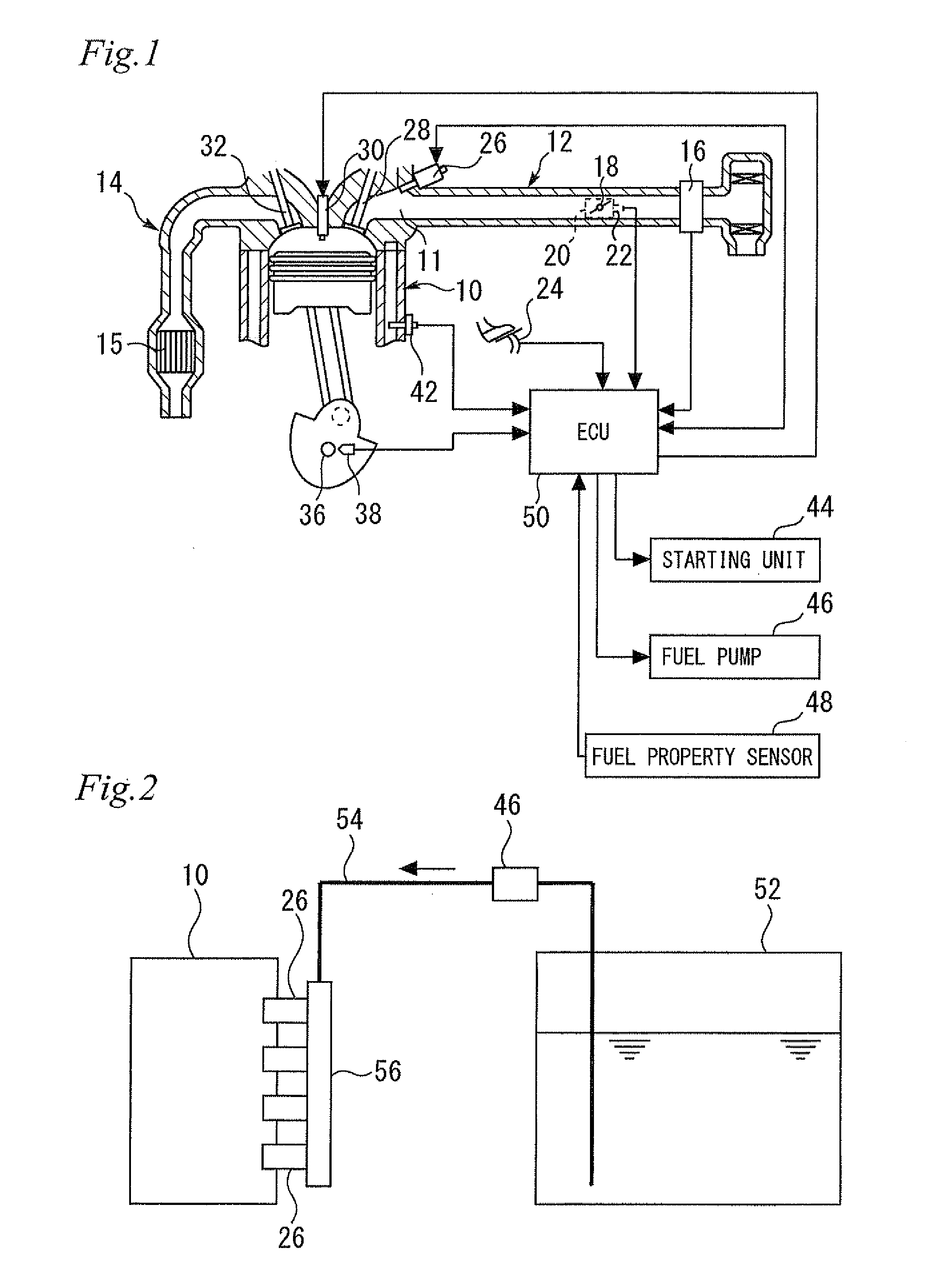
[0067]FIG. 1 is a diagram for illustrating a system configuration of a first embodiment of the present invention. Referring to FIG. 1, the system according to this embodiment includes an internal combustion engine 10. The internal combustion engine 10 is used, for example, as a driving power source for a vehicle. The internal combustion engine 10 of this embodiment is an in-line four-cylinder type; however, the number and arrangement of cylinders of the internal combustion engine according to the present invention are not specifically limited. FIG. 1 is a cross-sectional view of a single cylinder of the internal combustion engine 10.

[0068]The internal combustion engine 10 is operable on not only gasoline, but also a fuel that is a mixture composed of gasoline and ethanol, methanol, or other type of alcohol (hereinafter referred to also as an “alcohol-blended fuel” or a “blended fuel”). In this case, the alcohol-blended fuel may range from one having a low concentration (e.g. about s...

second embodiment

[0099]A second embodiment of the present invention will be described below with reference to FIG. 6. Differences from the first embodiment described above will be mainly described and descriptions of similarities will be simplified or omitted.

[0100]In this embodiment, when a predetermined fuel cut condition is satisfied, the ECU 50 performs a fuel cut control which brings fuel injection from the fuel injector 26 to a halt. For example, when the load requirement (torque requirement) of the internal combustion engine 10 is zero and the engine speed is equal to or larger than a predetermined speed, it is determined that deceleration fuel cut conditions are satisfied and deceleration fuel cut will be performed.

[0101]As described earlier, in a cold starting in the first embodiment, the high fuel pressure control is first performed to adsorb alcohol with the adsorbent 58, and after the internal combustion engine 10 has warmed up, the high fuel pressure control is switched to the low fuel ...

third embodiment

[0111]A third embodiment of the present invention will be described below with reference to FIGS. 7 to 9. Differences from the embodiments described above will be mainly described and descriptions of similarities will be simplified or omitted.

[0112]As described above, in the second embodiment, the alcohol is desorbed from the adsorbent 58 while performing fuel cut. The control error of the air-fuel ratio caused by desorption of the alcohol is thereby prevented from occurring.

[0113]Meanwhile, in this embodiment, the alcohol is desorbed from the adsorbent 58 during combustion operation of the internal combustion engine 10. In addition, the alcohol is desorbed when the engine speed and the engine load fall within predetermined ranges, described later, to thereby suppress occurrence of control errors of air-fuel ratio. FIG. 7 is a diagram showing a range in which desorption of alcohol is permitted in this embodiment with diagonal lines.

[0114]The fuel injection amount of the fuel injecto...


PUM


Abstract

A fuel injection apparatus for an internal combustion engine including a fuel injector having a leading end portion that has an internal space in which fuel is stored and an injection nozzle for injecting fuel; and an adsorbent disposed in the internal space, the adsorbent being capable of selectively adsorbing an alcohol component in a blended fuel of gasoline and alcohol. The adsorbent has a characteristic such that an amount of alcohol adsorption is small when a fuel pressure is low and large when the fuel pressure is high. Adsorption of alcohol onto, and desorption of alcohol from, the adsorbent can be controlled by changing the fuel pressure in the internal space.

Description

TECHNICAL FIELD[0001]The present invention relates to a fuel injection apparatus for an internal combustion engine.BACKGROUND ART[0002]A known internal combustion engine can use a blended fuel that is a mixture of gasoline and alcohol such as ethanol or methanol. FIG. 10 is a chart showing a relationship between a distillation rate and a temperature of E80 (a blended fuel with 80% ethanol), E20 (a blended fuel with 20% ethanol), and E0 (100% gasoline). Gasoline is composed of multiple components including one having a low boiling point which contributes to an outstanding vaporization characteristic even at low temperatures. Alcohol, on the other hand, is composed of a single component and thus has a fixed boiling point which is high (about 78° C. for ethanol). As is known from FIG. 10, therefore, a blended fuel having a high concentration of alcohol, such as E80, has a drawback that the fuel is extremely difficult to vaporize at temperatures lower than the boiling point of alcohol. ...

Claims


Application Information

Patent Timeline
Patent Type & Authority Patents(United States)
IPC IPC(8): F02M33/02
CPCF02M43/04
Inventor YOSHIOKA, MAMORUCHIBA, FUMITOTSUKAGOSHI, TAKAHIROONOE, RYOTA
Owner TOYOTA JIDOSHA KK
Why Eureka
Try Eureka