Switching power supply

a power supply and power supply technology, applied in the direction of electric variable regulation, process and machine control, instruments, etc., can solve the problem that the loss of fet during standby mode cannot be ignored

Active Publication Date: 2017-01-12
FUJI ELECTRIC CO LTD
View PDF7 Cites 14 Cited by
  • Summary
  • Abstract
  • Description
  • Claims
  • Application Information

AI Technical Summary

Benefits of technology

[0045]In addition, the main driver circuit only has to be controlled according to the enable signal, which is generated according to whether the power consumption of the load exceeds the predetermined threshold value. This makes it possible to continue to effectively utilize the basic features of conventional switching power supply control circuits as-is while also making it possible to effectively reduce switching loss in standby mode. Therefore, the present invention exhibits a variety of advantageous effects, such as making it possible to provide a simple switching power supply that effectively reduces power consumption in standby mode.

Problems solved by technology

However, if a FET having a power capacity that satisfies the desired power capacity rating for the switching power supply is used for the switching element Q, the switching loss in the FET during standby mode cannot be ignored.

Method used


Image

  • Switching power supply
  • Switching power supply
  • Switching power supply

Examples


Embodiment Construction

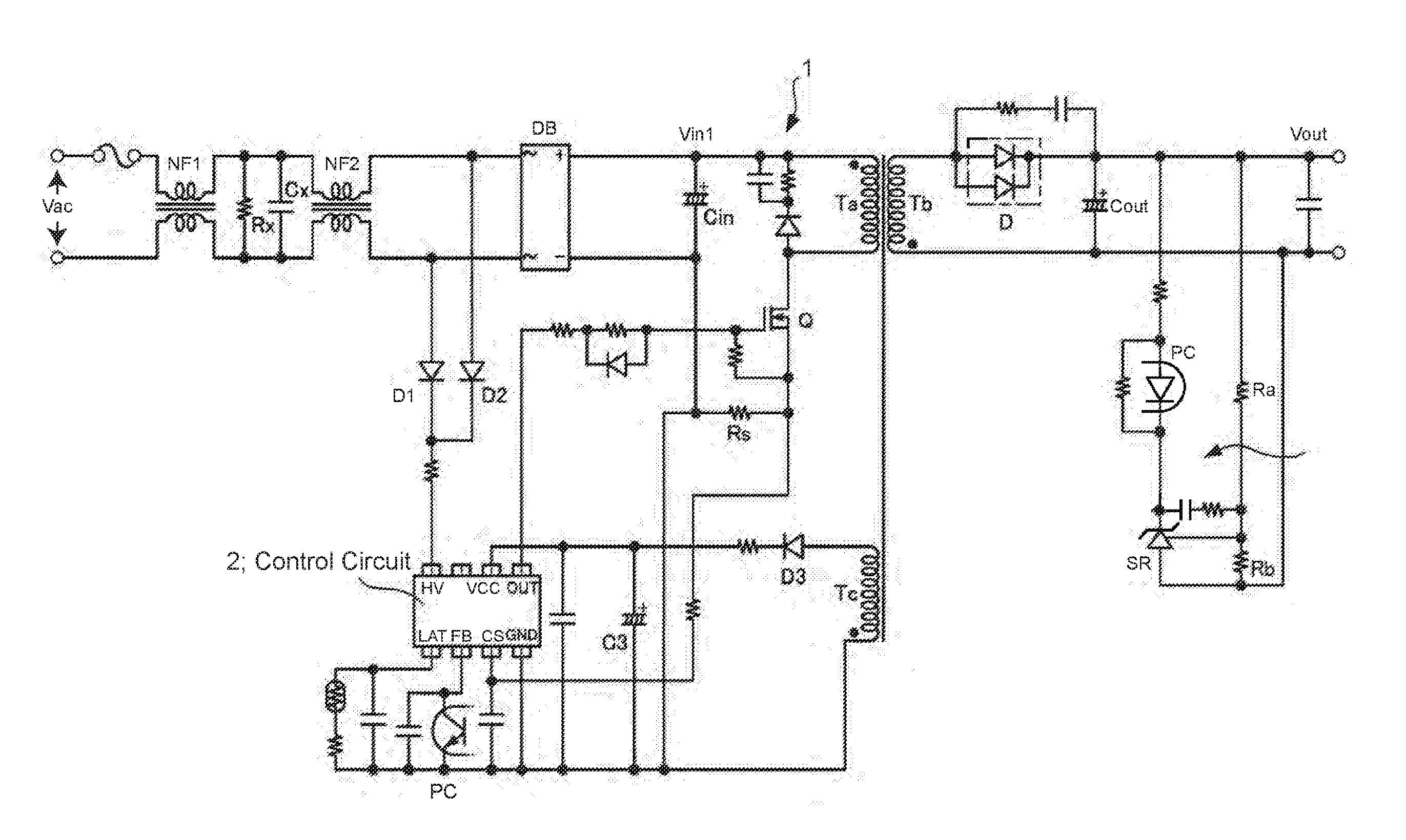
[0055]Next, a switching power supply according to an embodiment of the present invention will be described with reference to figures. The present invention is suitable for application to a switching power supply with a power capacity rating on the order of several dozen watts, for example.

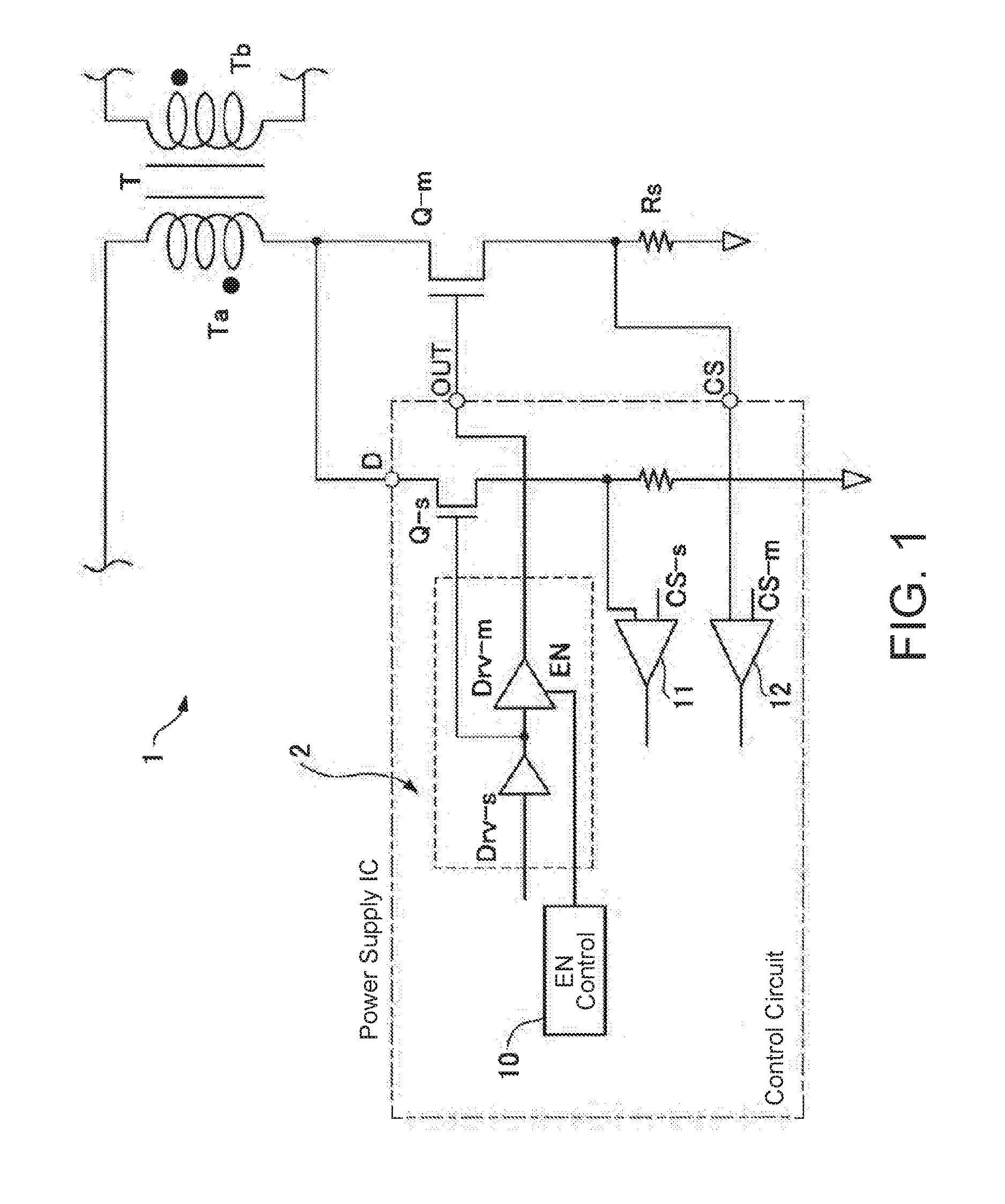
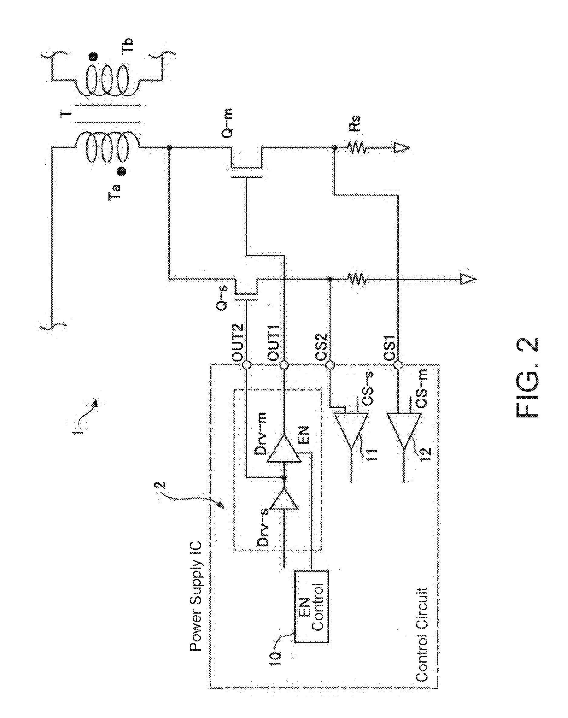
[0056]The switching power supply according to this embodiment of the present invention is substantially constituted by a secondary-side regulated flyback power supply device such as that illustrated in FIG. 4, for example. More specifically, as shown in the schematic illustrations of the main components of the configurations in FIGS. 1 and 2, the switching power supply includes a switching element Q that is connected in series to a primary coil Ta of a transformer T and is used as a main switching element Q-m for supplying power to a load (not illustrated in the figure) and a secondary switching element Q-s that is connected in parallel to the main switching element Q-m.

[0057]The main switching ele...


PUM


Abstract

A switching power supply includes a main switching element that is connected to a primary coil of a transformer and switches a main current ON / OFF, and a secondary switching element connected in parallel to the main switching element and that has a lower power capacity than the main switching element. The switching power supply also includes a control circuit that controls these switching elements. The control circuit includes: a main driver circuit that generates, in accordance with a control signal generated according to an output voltage from a secondary coil of the transformer, a main drive signal for switching the main switching element ON / OFF; a secondary driver circuit that generates a secondary drive signal for switching the secondary switching element ON / OFF according to the control signal; and an enable control circuit that deactivates the main driver circuit when a power consumption of a load is less than a threshold value.

Description

BACKGROUND OF THE INVENTION[0001]Technical Field[0002]The present invention relates to a switching power supply that has a simple configuration and makes it possible to reduce switching loss in a switching element as well as reduce power consumption while in a standby mode.[0003]Background Art[0004]One example of a switching power supply that can provide a rated power capacity on the order of several dozen watts is the flyback power switching circuit illustrated in FIG. 4. This type of switching power supply includes a diode bridge circuit DB that full-wave rectifies AC power supplied from a commercial 100V or 220V AC power source on the input side of the power switching circuit and an input capacitor Cin that smooths the output from the diode bridge circuit DB.[0005]As illustrated in FIG. 4, an AC power input line arranged upstream of the diode bridge circuit DB includes first and second noise filters NF1 and NF2 as well as a capacitor Cx in order to prevent high frequency conducti...

Claims


Application Information

Patent Timeline
Patent Type & Authority Applications(United States)
IPC IPC(8): H02M3/335H02M1/08
CPCH02M3/33523H02M2001/0009H02M2001/0032H02M1/08H02M3/33507Y02B70/10H02M1/0032H02M1/0009
Inventor NISHIJIMA, KENICHI
Owner FUJI ELECTRIC CO LTD
Why Eureka
Try Eureka