
Liquid treatment module

a technology of liquid treatment module and liquid treatment device, which is applied in the direction of centrifuges, separation processes, filtration separation, etc., can solve the problems of increasing the complexity of the treatment system, high price of ion exchange resin, and complex maintenance of equipment, so as to reduce the operating current, improve the liquid handling capability, and reduce the effect of operating curren

Inactive Publication Date: 2010-03-11
EST WATER & TECH
View PDF12 Cites 14 Cited by
  • Summary
  • Abstract
  • Description
  • Claims
  • Application Information

AI Technical Summary

Benefits of technology

[0011]The present invention provides the means to make a liquid treatment module that has a simple structure, can handle a large amount of fluid and has highly improved efficiency.
[0014]1) It can deal with a large quantity of liquid. The present invention only needs two power distribution panels, and a number of double-sided electrode plates are stacked between the two distribution panels. Lots of electrode plates could be placed for liquid treatment, so that the liquid handling capability is greatly improved.
[0016]3) Reliable connection. The present invention uses the package to bond, support, seal and insulate power distribution panels, double-sided electrode plates and the separators. The packaging not only conveniently provides the good insulation between the distribution plate and the double-sided electrode plates, but also fixes separators and the double-sided electrode plates at locations and improves the mechanical strength of the module.

Problems solved by technology

(1) Ion exchange: It uses ion exchange resins to treat liquid. The price of ion exchange resins is very high, and the process needs strong acids and alkali for resin regeneration, which produces secondary pollution. Moreover, the maintenance of the equipment is complicated.
(2) Reverse osmosis: This is the most commonly used industrial water purification method. It has advantages such as high desalination rate, simple process, etc. However, the macromolecule membranes are easily polluted and fouled by the organic substances, calcium and chlorine in water. It requires very restrictive pre-treatment system and the addition of several types of antioxidant and anti-scale inhibitor. These increase the complexity of the treatment system, and may cause troubles in system operation and maintenance.
(3) Electrodialysis: It is composed of the electrode plates, separation membrane, and ion exchange resins. Under the attraction forces of a DC electrical field, ions move through the membranes and are adsorbed on the ion exchange resins. However, the incorporated membranes are easily fouled, like in the reverse osmosis. Also, such treatment can only get rid of ions, and it has no effects on organic substances, colloid particles or other particles, or suspended solids. Moreover, the equipment consumes lots of energy due to the water electrolysis on the electrode plates.
1) It can only handle a small amount of liquid. Because there are lots of power distribution panels, there are only limited space left to accommodate the electrode plates for liquid treatment. Hence the total handling capacity is limited;
2) The module structure is complex. Because the system requires multiple power distribution plates, each of which requires its own component, the reliability is reduced; and
3) Operating current is very large. The power distribution plates are connected to the DC power supply through their own distribution components. The large working current requires large power supply system, and thus, the manufacturing costs of the treatment devices increase.

Method used


Image

  • Liquid treatment module
  • Liquid treatment module
  • Liquid treatment module

Examples


Embodiment Construction

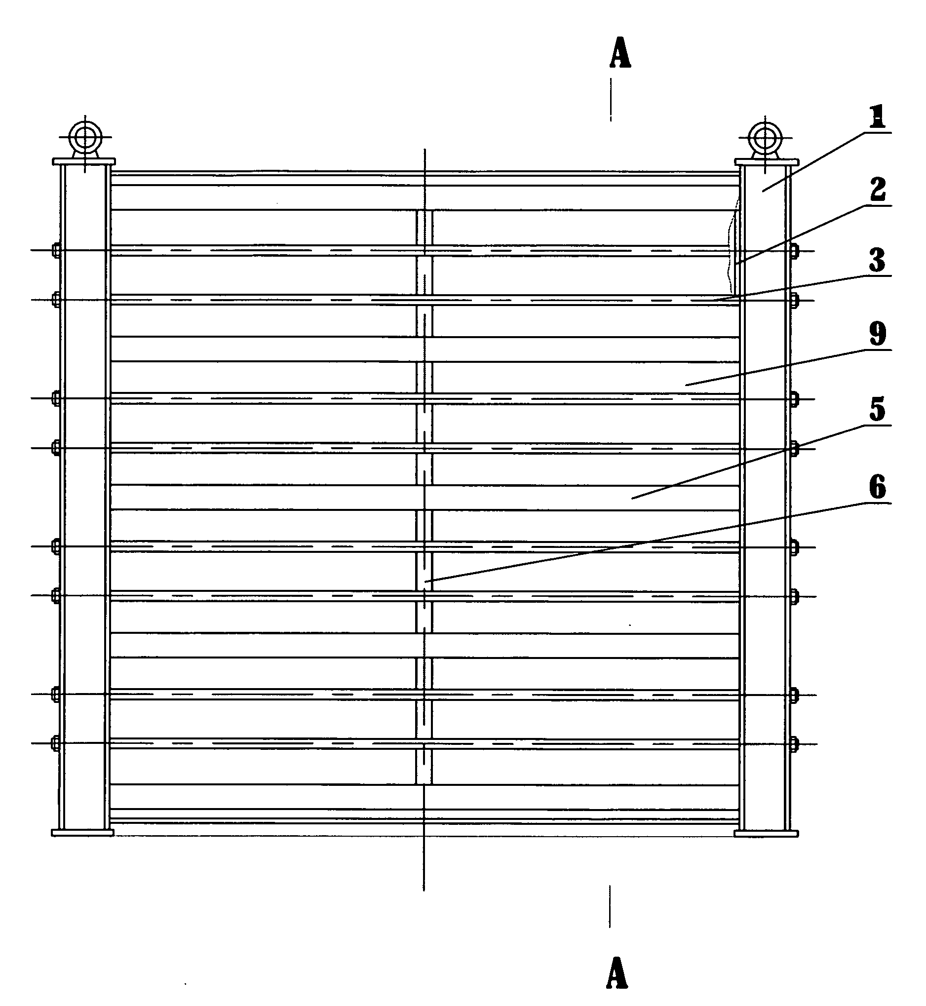
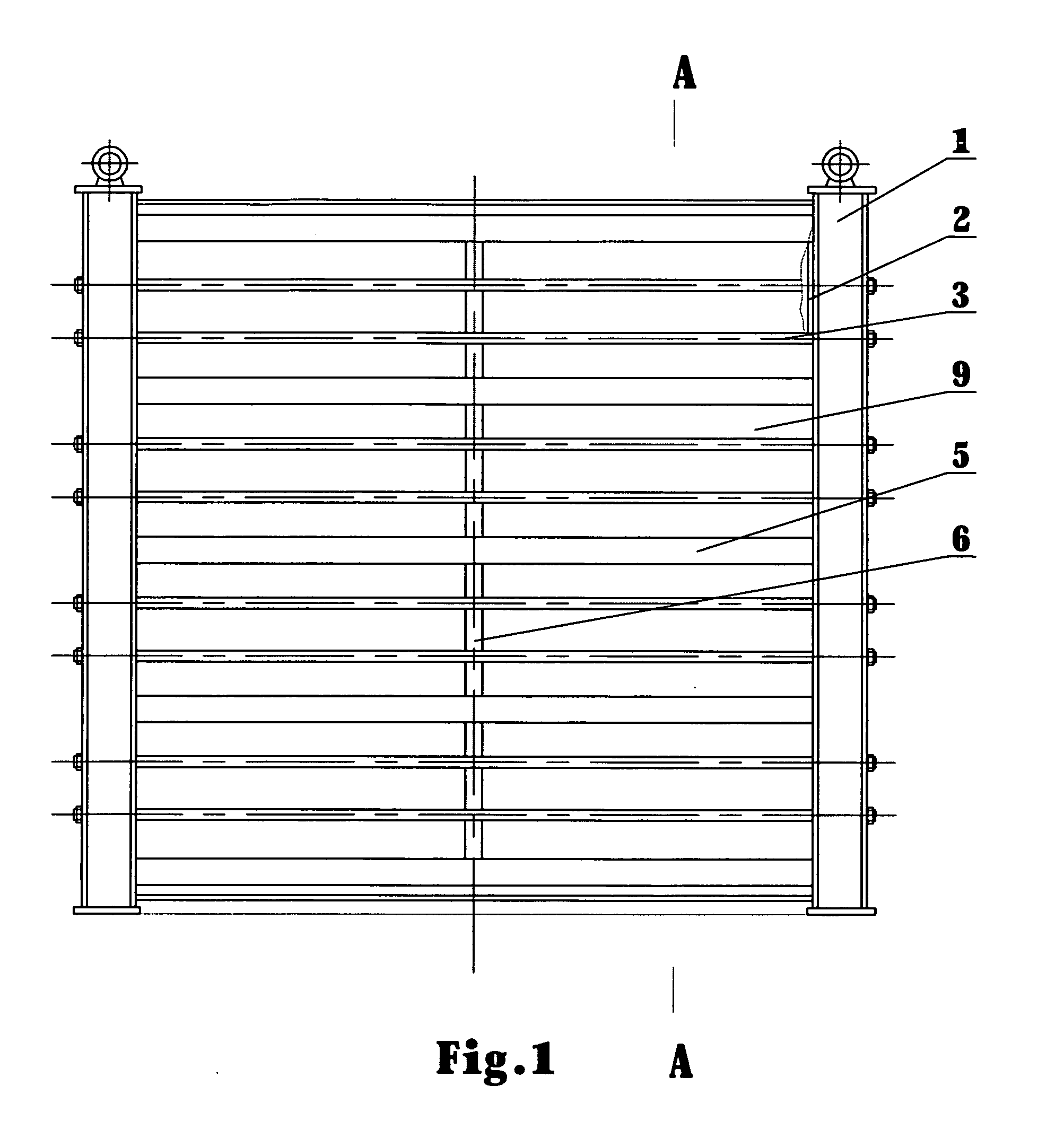
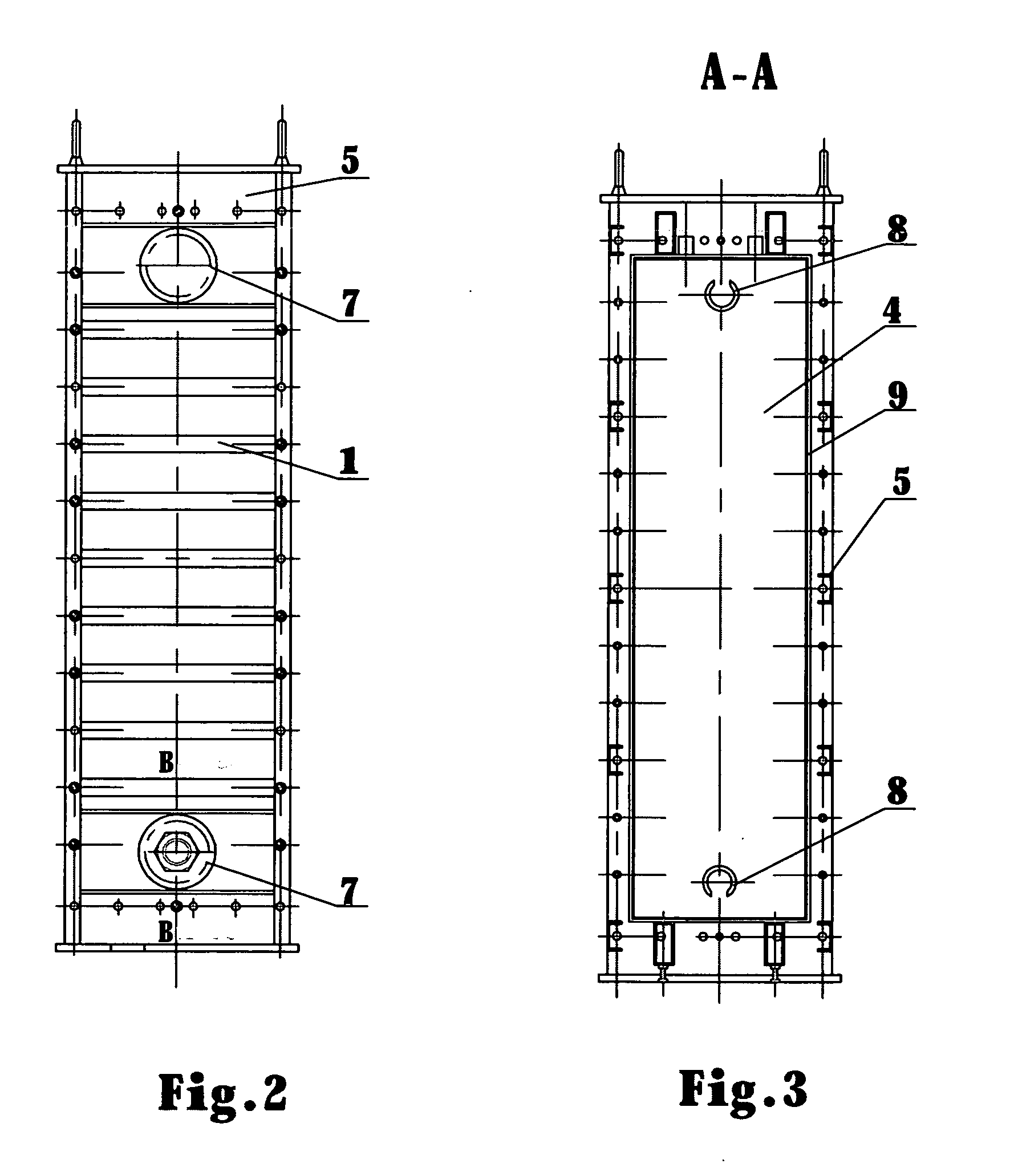
[0030]The liquid treatment device of the present invention is shown in FIGS. 1 to 4, including the power distribution panels 2, electrode plates, and frameworks 5 with two side end plates 1.

[0031]As shown in FIG. 1, the two power distribution panels 2 are connected to the end plates 1 through the connector 3. Inside of the power distribution panels 2 is the electrode plate 24. The power distribution plates 2 are connected with the DC power supply through electrical wires. The power distribution panels 2 of the present invention may be conductive metal plates, and connect to the DC power supply through the electrical wires.

[0032]Alternatively, as shown in FIGS. 5 and 6, the power distribution plate can be made of the insulation plates 21 and sequentially on top of the inner side of the insulation plate 21, the conductive plate 22, the collector plate 23 and the electrode plate 24. There is also a transition layer 26 on the surface of the electrode plates 21. The conductor 22 is ancho...


PUM

PropertyMeasurementUnit
Flow rateaaaaaaaaaa
Electrical conductoraaaaaaaaaa

Abstract

The present invention relates to a liquid treatment module, which comprises power distribution panels, electrode plates and a framework with side plates. The two power distribution panels are fixed on the two side plates. The power distribution panels have electrode plates located on inner side of the panels. There are two or more double-sided electrode plates placed in stacks between the two distribution panels which are connected to the DC power supply through the electric wires. There are separators placed between the adjacent electrode plates to provide the flow channels. Each flow channel is connected with the inlet and outlet holes on the side plates. The exposed surface of the power distribution panels, double-sided electrode plates and the separators are bonded and sealed by the insulating package. This invention has characteristics of simple structure, large liquid handling capacity, high efficiency, and can be used to process liquids of various kinds including water, wine, fruit juices, beverages, dairy products and chemical wastes from various sources for impurities removal.

Description

TECHNICAL FIELD[0001]This invention relates to modules of a liquid treatment device for impurity removal.TECHNICAL BACKGROUND[0002]There are many methods for liquid treatments to remove impurities, especially for water treatment. Typical treatment methods include distillation, reverse osmosis, electrodialysis, ion exchange, and freezing. Among them, the major methods utilized for large industrial scale applications include:[0003](1) Ion exchange: It uses ion exchange resins to treat liquid. The price of ion exchange resins is very high, and the process needs strong acids and alkali for resin regeneration, which produces secondary pollution. Moreover, the maintenance of the equipment is complicated.[0004](2) Reverse osmosis: This is the most commonly used industrial water purification method. It has advantages such as high desalination rate, simple process, etc. However, the macromolecule membranes are easily polluted and fouled by the organic substances, calcium and chlorine in wate...

Claims


Application Information

Patent Timeline
IPC IPC(8): B03C5/02
CPCA23L2/70C02F1/46104C02F2201/4617C02F2001/46128C02F2001/46152C02F1/469
Inventor SUN, XIAOWEISUN, XIAOMINGSHAO, HUANQINGZHAN, BORONG
Owner EST WATER & TECH
Learn More