
Iron

a technology of ironing board and ironing board, which is applied in the field of irons, can solve the problems of unsuitable traditional ironing involving a large standard ironing board, inability to move large amounts of clothing or fabric items, and inability to move an ironing board around the retail environment, and achieve the effect of fast ironing

Active Publication Date: 2017-02-28
FORD WILLCOCKS HARRY
View PDF11 Cites 0 Cited by
  • Summary
  • Abstract
  • Description
  • Claims
  • Application Information

AI Technical Summary

Benefits of technology

The present invention is a fabric iron that can be used without an ironing board. The device has a unique grip handle arrangement that allows it to be closed with a single hand, even if the first and second arm bodies are too far apart. The device also has two heating plates that heat the fabric on both sides simultaneously, resulting in faster ironing compared to traditional irons that heat only one side. The iron has an open and closed configuration, and it can be opened by separating the first and second arm bodies, and closed by bringing the first and second arm bodies into contact with each other. The fixed ends describe the pivoted ends.

Problems solved by technology

Traditional ironing involving a large standard iron and ironing board can be unsuitable in many situations, particularly where travellers are unable to transport a bulky iron or ironing board.
In a retail environment, it is impractical to move large amounts of clothing or fabric items to an iron and ironing board and it is impractical to move an iron and ironing board around the retail environment.
It is difficult to move certain fabric items, such as curtains, to an iron and ironing board set up.
Small sized standard irons are available and are sufficiently portable for travellers, however they disadvantageously still require an ironing board or similar surface.
Steamers are available providing a flow of steam or water vapour for easing creases from fabric, however current steamers are unsatisfactory as they are bulky and unable to apply high temperature or pressure to the fabric to be ironed.
However, such hand held fabric irons are only able to iron small items or the edges of larger items.

Method used


Image

  • Iron
  • Iron
  • Iron

Examples


Embodiment Construction

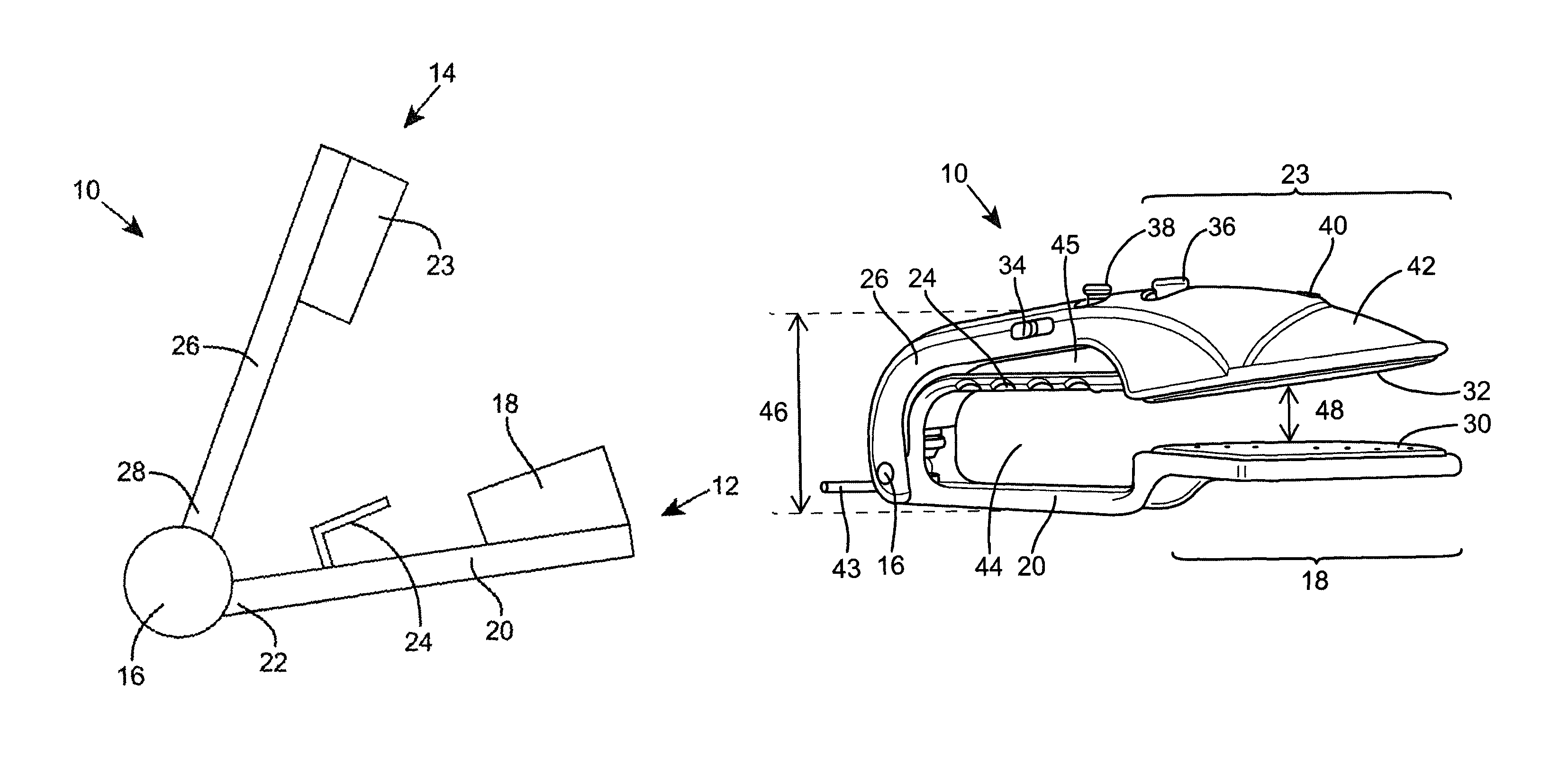
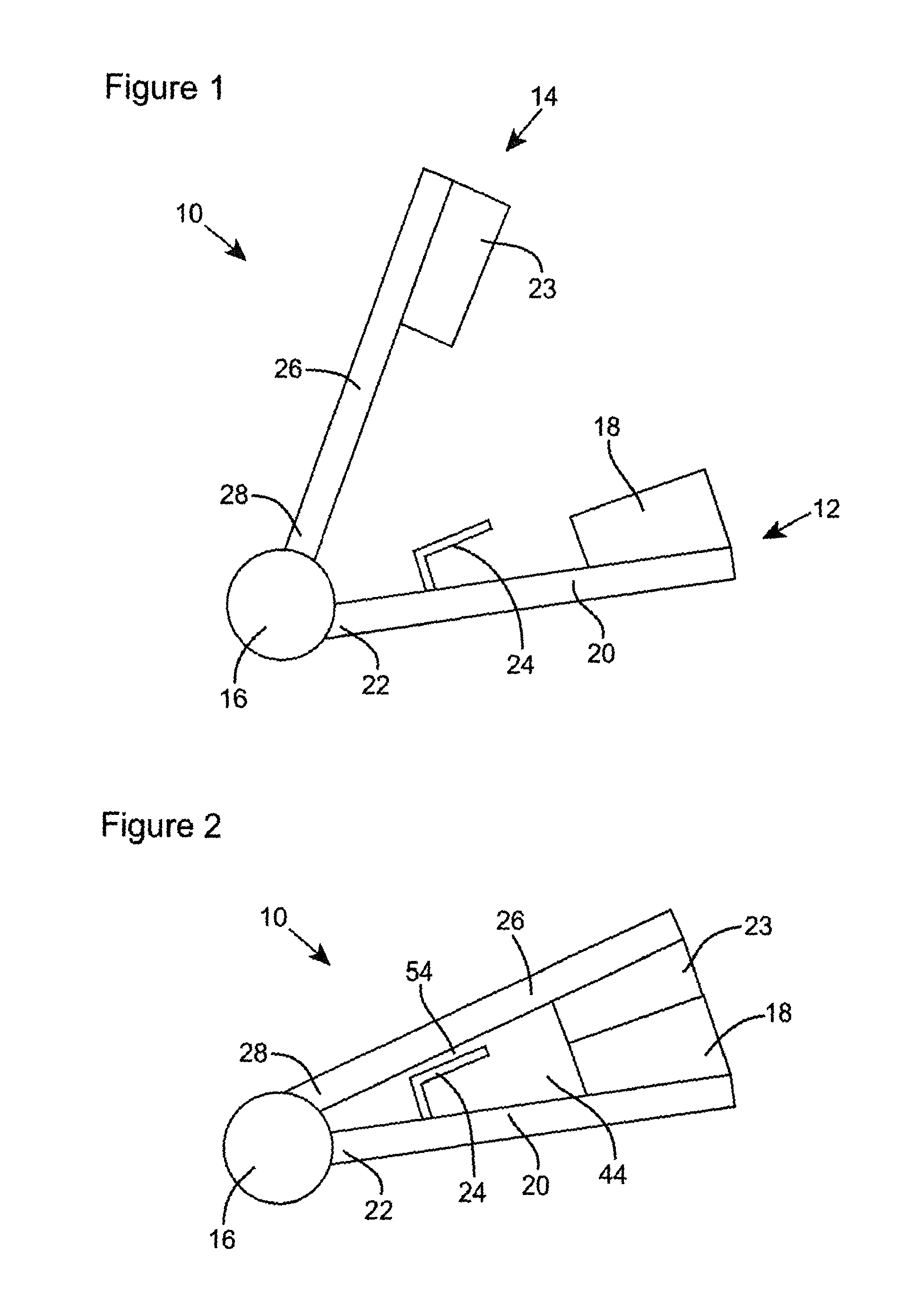
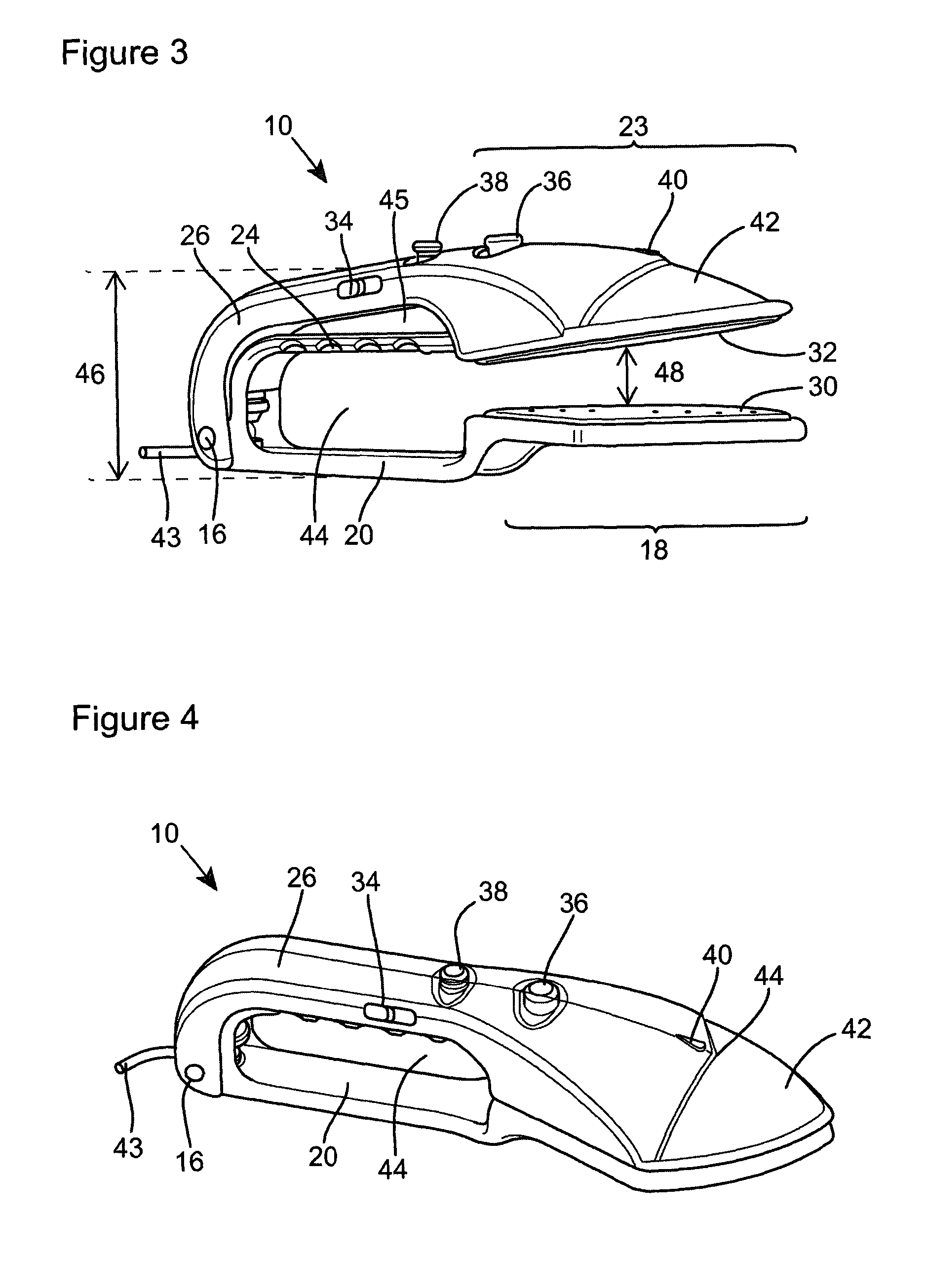
[0037]Referring now to the drawings, where in all figures like numerals refer to like components, FIGS. 1 and 2 illustrate an embodiment of the invention. FIGS. 3 and 4 illustrate a preferred embodiment of the invention. FIGS. 5, 6 and 7 illustrate a preferred embodiment of the invention in open and closed configurations. FIGS. 8 and 9 illustrate a preferred embodiment of the cushioning pads for one of the heating plates in the invention. FIG. 10 illustrates a preferred embodiment of a door hanger. For clarity, not all components are labelled on all figures.

[0038]FIG. 1 illustrates an iron 10 of the invention in an open configuration. The iron includes a first arm 12, a second arm 14 and a pivot 16. First arm 12 includes a first arm opposing portion 18, a first arm body 20, a first arm pivoted end 22, and a grip handle 24. Second arm 14 includes a second arm opposing portion 23, a second arm body 26, and a second arm pivoted end 28. In the open configuration first arm opposing porti...


PUM


Abstract

An iron (10) which comprises a first arm (12) mounted to a second arm (14) about a pivot (16); where the first arm (12) includes a first arm body (20), a first arm opposing portion 18 and a grip handle (24); and the second arm (14) includes a second arm body (26) and a second arm opposing portion (23); where at least a portion of the grip handle (24) of the first arm (12) extends away from the first arm body (20) towards the second arm (14); with the first and second arms being movable about the pivot (16) between an open configuration in which the first arm opposing portion (18) is separated from the second arm opposing portion (23), and a closed configuration, in which the first arm opposing portion (18) is in contact with the second arm opposing portion (23); wherein movement of the second arm (14) towards the grip handle (24) brings the iron into the closed configuration from the open configuration.

Description

CROSS-REFERENCE TO RELATED APPLICATIONS[0001]This application is a National Stage of International Application No. PCT / GB2014 / 051163, filed Apr. 14, 2014, which in turn claims priority to Great Britain Patent Application No. GB1310535.8, filed Jun. 13, 2013, and Great Britain Patent Application No. GB1306718.6, filed Apr. 12, 2013. The entire disclosures of the above applications are hereby incorporated herein by reference.FIELD OF THE INVENTION[0002]The present invention relates to an iron, and particularly to a portable grip iron suitable for ironing or pressing, for example, clothes and curtains.BACKGROUND TO THE INVENTION[0003]Traditional ironing involving a large standard iron and ironing board can be unsuitable in many situations, particularly where travellers are unable to transport a bulky iron or ironing board. In a retail environment, it is impractical to move large amounts of clothing or fabric items to an iron and ironing board and it is impractical to move an iron and i...

Claims


Application Information

Patent Timeline
Patent Type & Authority Patents(United States)
IPC IPC(8): D06F75/00D06F75/34D06F87/00A45D2/00D06F75/30
CPCD06F75/30A45D2/00A45D2/001D06F75/00D06F75/34D06F87/00
Inventor FORD-WILLCOCKS, HARRY
Owner FORD WILLCOCKS HARRY
Learn More