
Dialysis apparatus

a technology of dialysis apparatus and dialysis liquid, which is applied in the direction of chemistry apparatus and processes, separation processes, liquid degasification, etc., can solve the problems of air bubble generation and liquid becoming inability to be fed, and achieve the effect of preventing reliable production

Active Publication Date: 2017-03-14
SHIBUYA IND CO LTD
View PDF14 Cites 1 Cited by
  • Summary
  • Abstract
  • Description
  • Claims
  • Application Information

AI Technical Summary

Benefits of technology

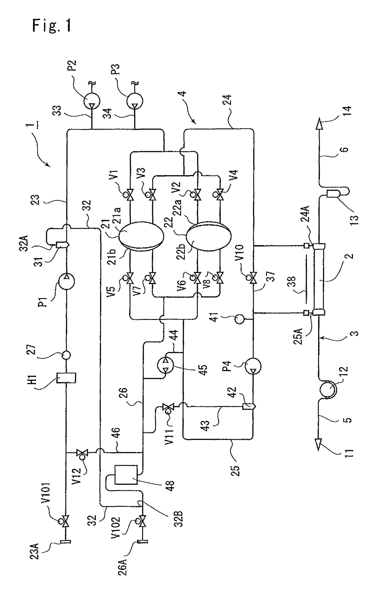
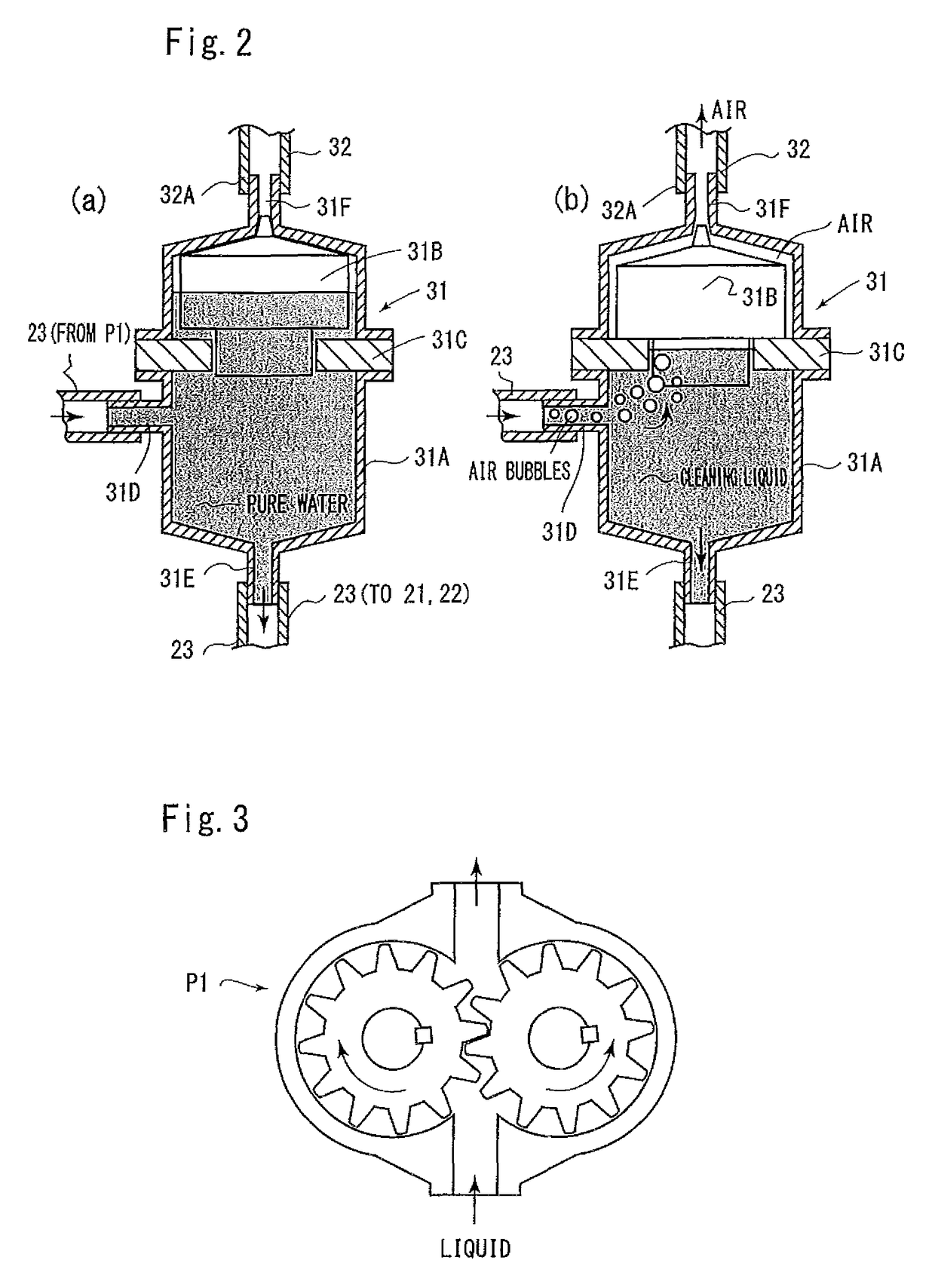
[0016]According to the invention (1), the air bubbles generated when the heated cleaning liquid is circulated is discharged into the gas storage unit from the deaeration tank via the deaeration passage and is stored therein. Thus, the air bubbles are prevented from being entrained in the pump so that the pump can reliably be prevented from being unable to feed a liquid.
[0017]According to the invention (2), the cleaning liquid is fed to the gas storage tank from the liquid discharge passage via the connection port in the lower part of the gas storage tank, and the cleaning liquid and air can be discharged into a distal end of the liquid discharge passage via the connection port in the upper part of the gas storage tank. Thus, the inside of the gas storage tank can be cleaned with the cleaning liquid.

Problems solved by technology

However, when the heated hot water serving as the cleaning liquid is circulated through the liquid circuit, air bubbles are generated from the hot water.
When air bubbles in a large amount are eventually entrained in a pump, a liquid becomes unable to be fed.

Method used


Image

  • Dialysis apparatus
  • Dialysis apparatus
  • Dialysis apparatus

Examples


Embodiment Construction

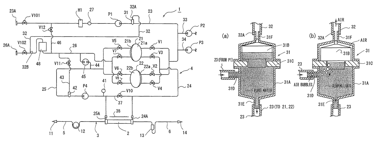
[0022]The present invention will be described below for an illustrated embodiment. In FIG. 1, reference numeral 1 denotes a dialysis apparatus for subjecting a patient to dialysis treatment. This dialysis apparatus 1 includes a dialyzer 2 that performs hemodialysis, a blood circuit 3 connected to the dialyzer 2, and a dialysate circuit 4 connected to the dialyzer 2. Control means (not illustrated) controls the components in the dialysis apparatus 1.

[0023]The dialyzer 2 has conventionally been well-known. The inside of the dialyzer 2 is partitioned into a blood chamber and a dialysate chamber through a hollow fiber membrane (not illustrated). Blood flows through the blood chamber while a dialysate flows through the dialysate chamber.

[0024]The blood circuit 3 includes an artery-side passage 5 connected to the artery of the patient and connected to one end of the dialyzer 2, and a vein-side passage 6 connected to the vein of the patient and connected to the other end of the dialyzer 2....


PUM

PropertyMeasurementUnit
timeaaaaaaaaaa
temperatureaaaaaaaaaa
diameteraaaaaaaaaa

Abstract

A dialysis apparatus has a dialysate circuit 4 which is cleaned after dialysis by both opening / closing valves V101 and V102 being closed after a dialysate in the dialysate circuit 4 is replaced with a cleaning liquid. The opening / closing valve V12 is opened, and the cleaning liquid is circulated by pumps P1 and P4 while being heated by a heater H1, to clean the inside of the dialysate circuit 4. A deaeration tank 31 is provided downstream of the pump P1. Air bubbles generated from the cleaning liquid serving as hot water are deaerated by the deaeration tank 31 and are then discharged into a gas storage tank 48 via a deaeration passage 32. The pumps P1 and P4 can be reliably prevented from being unable to operate with the air bubbles generated from the cleaning liquid.

Description

TECHNICAL FIELD[0001]The present invention relates to a dialysis apparatus, and more specifically, to a dialysis apparatus adapted to clean a dialysate circuit by circulating a heated cleaning liquid therethrough.BACKGROUND ART[0002]In a hospital where a dialysis apparatus subjects a patient to dialysis treatment, a dialysate circuit is cleaned at a required timing such as a time point where one day ends or treatment for one patient ends. Conventionally, a technique for cleaning a liquid circuit by circulating hot water therethrough has been known (e.g., Patent Literature 1).[0003]In an apparatus in Patent Literature 1, hot water heated by a heating device 9 is circulated through the liquid circuit in a state where both valves 21 and 24 are closed after the liquid circuit is filled with a cleaning liquid while a valve 26 in a short-circuit 25, which bypasses an inlet pipe 1 and a return circuit distal end 2, is opened.[0004]However, when the heated hot water serving as the cleaning ...

Claims


Application Information

Patent Timeline
Patent Type & Authority Patents(United States)
IPC IPC(8): A61M1/16B01D19/00
CPCA61M1/1658A61M1/1686A61M1/1688B01D19/0042
Inventor MISHIMA, TAKASHISAITO, SHINGO
Owner SHIBUYA IND CO LTD
Learn More