

Dialysis apparatus
a technology of dialysis apparatus and dialysis liquid, which is applied in the direction of liquid degasification, separation process, filtration separation, etc., can solve the problems of air bubble generation and liquid becoming inability to be fed, and achieve the effect of preventing reliable production
- Summary
- Abstract
- Description
- Claims
- Application Information
AI Technical Summary
Benefits of technology
Problems solved by technology
Method used
Image

Examples
Embodiment Construction
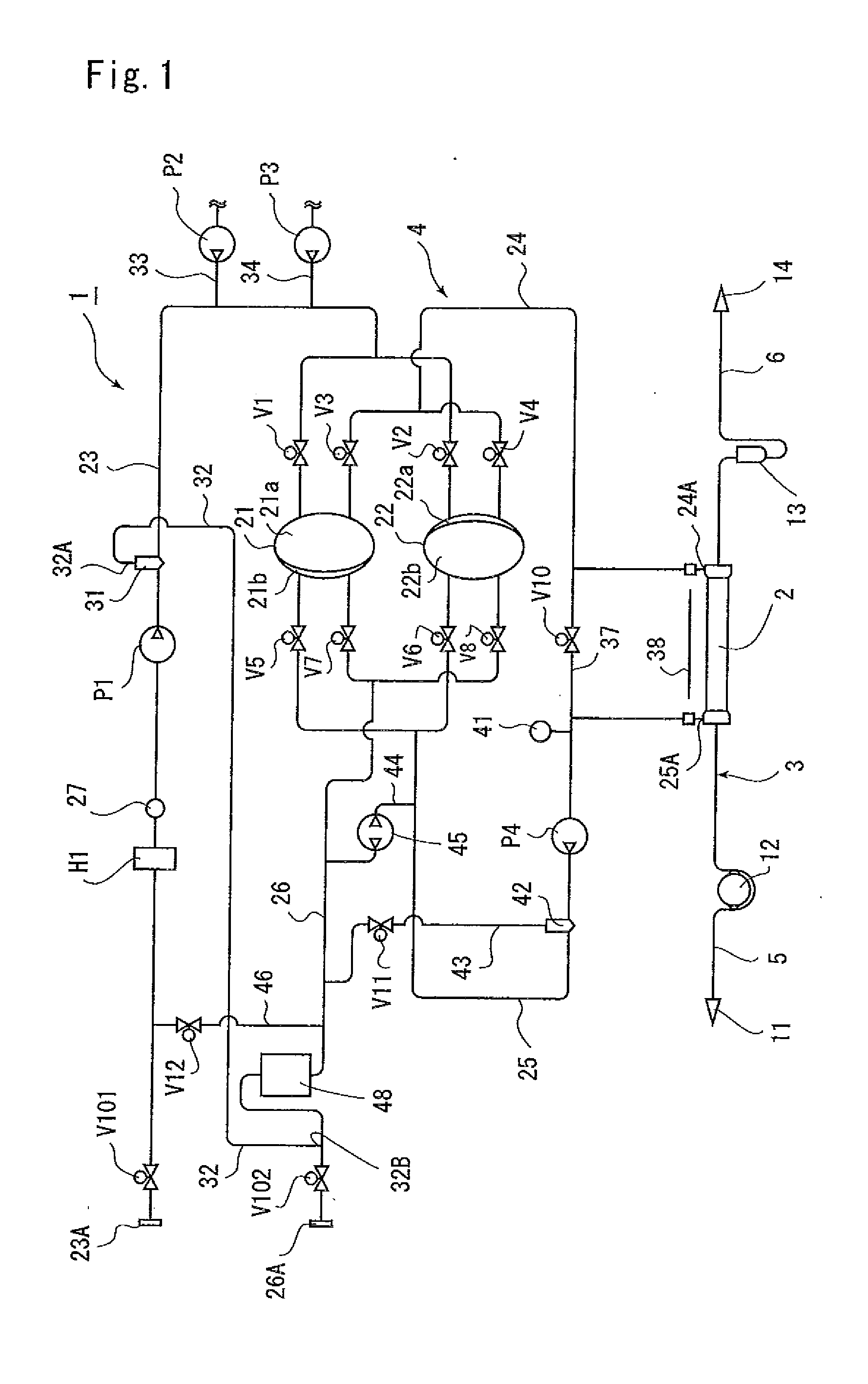
[0019]The present invention will be described below for an illustrated embodiment. In FIG. 1, reference numeral 1 denotes a dialysis apparatus for subjecting a patient to dialysis treatment. This dialysis apparatus 1 includes a dialyzer 2 that performs hemodialysis, a blood circuit 3 connected to the dialyzer 2, and a dialysate circuit 4 connected to the dialyzer 2. Control means (not illustrated) controls the components in the dialysis apparatus 1.
[0020]The dialyzer 2 has conventionally been well-known. The inside of the dialyzer 2 is partitioned into a blood chamber and a dialysate chamber through a hollow fiber membrane (not illustrated). A blood flows through the blood chamber while a dialysate flows through the dialysate chamber.
[0021]The blood circuit 3 includes an artery-side passage 5 connected to the artery of the patient and connected to one end of the dialyzer 2, and a vein-side passage 6 connected to the vein of the patient and connected to the other end of the dialyzer ...
PUM
 Abstract
Description
Claims
Application Information