Method and device for detection of a fault in a protected unit

a protection unit and fault detection technology, applied in the field of power systems, can solve problems such as dc line shut down, and failure of dc line, and achieve the effect of high speed

Active Publication Date: 2017-04-11
HITACHI ENERGY LTD
View PDF12 Cites 6 Cited by
  • Summary
  • Abstract
  • Description
  • Claims
  • Application Information

AI Technical Summary

Benefits of technology

[0013]Sensing a current in the at least one current path in the protected unit, e.g. at one end of the protected unit, during a plurality of different time periods, thereby obtaining a plurality of sensed currents, and determining compliance of at least one of the sensed currents with a respective first current criteria based on a first current threshold value, may facilitate or enable detection of whether a fault, e.g. a permanent fault, in the at least one current path or protected unit, e.g. at one end of the protected unit, is present or exists at a certain point in time. The point in time can be immediately after the protected unit has been reconnected to at least a portion of the rest of the power system, or relatively close in time to after the protected unit has been reconnected to at least a portion of the rest of the power system, e.g. immediately following auto reclosing of the circuit breakers or relatively close in time to after auto reclosing of the circuit breakers, or following energization of the at least one current path in the protected unit.
[0015]Embodiments of the present invention may allow utilizing circuit breaker auto reclosing on protected units such as DC OHLs in power systems. By utilizing circuit breaker auto reclosing on DC OHLs it may not be necessary to shut down the DC line or DC link whenever a fault occurs in the power system, e.g. a DC grid. Auto reclosing circuit breakers on a DC line may reduce or even minimize the outage time of the DC line, which may improve the overall operation of the entire power system at least with respect to reducing or minimizing time when not in operation. As will become further evident from the following description, the generated signal or signals may be utilized in determining whether to disconnect the protected unit from at least a portion of the rest of the power system.
[0023]When a protected unit such as a DC line is restored back to normal operation following successful auto reclosing, and there is no fault in the DC line, the line side voltage will initially ‘jump’ to the rated DC line voltage, and then oscillate about the rated DC line voltage, due to the nature of an RLC circuit, as known to a person skilled in the art. Eventually the line side voltage will be at or substantially at the rated DC line voltage after steady state conditions have been reached. The sensing of the voltage, determination of the sensed voltage with the voltage criteria and generation of a signal as described above may be referred to as an overvoltage blocking functionality. Implementing such functionality may facilitate or even enable using relatively sensitive settings for the signalling based on sensing current in the at least one current path in the protected unit during a plurality of different time periods, whereby a plurality of sensed currents are obtained, e.g. facilitating or even enabling use of a relatively sensitive first current criteria based on a first current threshold value.
[0034]By sensing a current in the at least one current path in the protected unit during different respective time instants, e.g. during at least three different respective time instants (t1−t0), (t2−t0), (t3−t0) as described in the foregoing, detection of fault in the protected unit with speed faster than so called over-current protection schemes may be facilitated, and / or detection of any fault occurring over the whole or substantially the whole of the length of the at least one current path, with relatively high speed and / or speed comparable to a speed of a primary protection system for detecting faults in such a protected unit, may be facilitated.

Problems solved by technology

On the other hand, in transmission lines based solely on cables, virtually all faults are permanent faults, and auto-reclosing is therefore not applied.
However, if the fault is a permanent fault, the DC line will be shut down again after reclosing it.
Events leading to DC line faults could happen both during normal operation when the DC line is energized, or when the DC line is not energized.
In case the DC line is not energized when the fault occurs, the fault may only manifest itself when the DC line is attempted to be brought back into service or operation.
In case of permanent faults however, the DC circuit breakers need to be tripped again after auto reclosing since there may still be a fault present in the DC line.

Method used


Image

  • Method and device for detection of a fault in a protected unit
  • Method and device for detection of a fault in a protected unit
  • Method and device for detection of a fault in a protected unit

Examples


Embodiment Construction

[0057]The present invention will now be described more fully hereinafter with reference to the accompanying drawings, in which exemplifying embodiments of the present invention are shown. The present invention may, however, be embodied in many different forms and should not be construed as limited to the embodiments set forth herein; rather, these embodiments are provided by way of example so that this disclosure will convey the scope of the invention to those skilled in the art. Furthermore, like numbers refer to like or similar elements or components throughout. The steps of any method described herein do not have to be performed in the exact order as described, unless specifically stated.

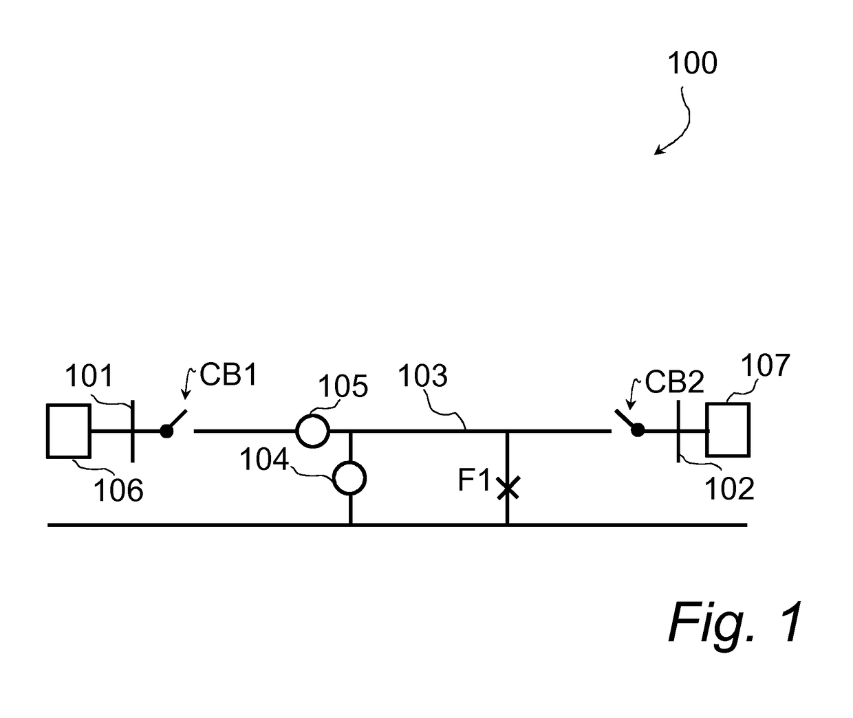
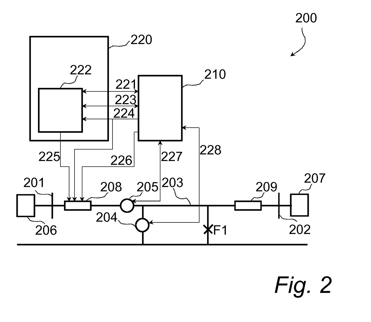
[0058]In DC grid systems, fault isolation is anticipated to be carried out utilizing DC circuit breakers without shutting down converters. Such a strategy is intended to preserve the integrity of the DC grid by allowing rerouting of DC power through other, non-faulty, DC lines. Even remote faults...


PUM


Abstract

A method to facilitate fault detection in the protected unit after connection to the at least a portion of the power system. A current is sensed in the protected unit during a plurality of different time periods. Compliance of at least one of the sensed currents with a respective first current criteria is determined based on a first current threshold value. On a condition that there is determined that at least one of the sensed currents comply with the respective first current criteria, a fault in the protected unit is detected.

Description

FIELD OF THE INVENTION[0001]The present invention generally relates to power systems, e.g. power transmission systems. Specifically, the present invention relates to fault detection in a protected unit included in a power system, which protected unit for example may comprise a power transmission line, such as a direct current (DC) power transmission line, which may be a DC overhead line (OHL).BACKGROUND OF THE INVENTION[0002]In overhead transmission lines or overhead lines (OHL) auto-reclosing protection may be utilized. A fault protection or detection unit may be employed for monitoring one or several transmission lines of a power transmission network. In the event of a fault on a transmission line, the fault protection unit trips circuit breakers located at each end of the transmission line, for the purpose of disconnecting the transmission line having a fault from the rest of the power transmission network. Thereby, the risk of propagation of the fault in the power transmission n...

Claims


Application Information

Patent Timeline
Patent Type & Authority Patents(United States)
IPC IPC(8): H02H3/06G01R31/40H02H7/26H02H3/087G01R31/02G01R31/50
CPCG01R31/40G01R31/025H02H3/087H02H7/268G01R31/52G01R31/50
Inventor NUQUI, REYNALDOPAN, JIUPINGWANG, JIANPING
Owner HITACHI ENERGY LTD
Why Eureka
Try Eureka