Relieving congestion in wireless local area networks

a wireless local area network and congestion relief technology, applied in the field of wireless local area networks or wlans, can solve the problems of simultaneous access (collisions) of clients, degradation of client experience quality, inconvenience of users, etc., and achieve the effect of maximizing the potential achievable data rate of each client and relievering network congestion problems

Inactive Publication Date: 2017-05-02
FUJITSU LTD
View PDF6 Cites 8 Cited by
  • Summary
  • Abstract
  • Description
  • Claims
  • Application Information

AI Technical Summary

Benefits of technology

[0054]According to a fourth aspect of the present invention, there is provided computer-readable code which, when executed by a processor of a computer connected to access points of a WLAN, causes the computer to perform the method defined above.
[0058]Thus, embodiments can provide a traffic congestion estimation method used for Wi-Fi based wireless networks. Based on measuring how busy the wireless channel of certain AP is and the single user transmission rate resulted from a specific radio link, an association criterion and a centralized algorithm are provided that can be used by a central association server to help active clients pick up suitable APs to be associated with. The centralized association algorithm aims at maximizing each client's potentially achievable data rate. With the intelligent management of clients' association pattern, the clients' QoE is improved and the network's congestion problems are relieved.

Problems solved by technology

On the other hand, using the same channel for all the wireless devices of an AP leads to the possibility of simultaneous access (collisions) by clients.
Attempts have been made to achieve load balancing among APs, but these generally involve causing an AP which is highly-loaded to refuse to accept further connections, which causes inconvenience to users.
However, this can result in some RATs and APs become more congested than the others which will cause the degradation in quality of experience (QoE) of clients.

Method used


Image

  • Relieving congestion in wireless local area networks
  • Relieving congestion in wireless local area networks
  • Relieving congestion in wireless local area networks

Examples


Embodiment Construction

[0066]An embodiment will now be described by way of example, referring to Wi-Fi, although it is to be understood that the embodiment is also applicable to other types of WLAN operating on the same principles.

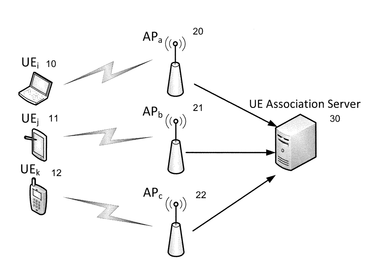
[0067]Methods of the embodiment are based on centralized system architecture, which in a simplified form is shown in FIG. 4. A plurality of APs 20, 21 and 22 are deployed in a WLAN to form overlapping hotspots within an enterprise, for example. A central association server 30 is connected to the APs by broadband cable for example (in practice, at least one network switch would be interposed between the central association server and APs). The central association server controls the WLAN at an enterprise level, for example. Thus, different WLANs would normally each have their own central association server. The central association server may have various functions apart from performing the method; for example it may perform other load balancing operations outside the scope of the...


PUM


Abstract

A wireless local area network, WLAN, comprising: access points arranged to maintain wireless links with terminals each arranged to initiate a wireless link with an access point, and to associate with an access point during a service session. A central association server is connected to each of the access points, and is arranged to gather information from a plurality of the terminals via the wireless links between terminals and access points, determine, based on the gathered information, with which access point a terminal which has initiated a wireless link should associate during its service session, and notify the terminal, via the access point with which the terminal initiated the wireless link, of the access point so determined.

Description

CROSS-REFERENCE TO RELATED APPLICATIONS[0001]This application claims the benefit of European Application No. 13161442.2, filed Mar. 27, 2013, the disclosure of which is incorporated herein by reference.BACKGROUND[0002]1. Field[0003]The embodiments relate to wireless local area networks or WLANs, and more particularly WLANs capable of operating in accordance with IEEE802.11 standards.[0004]2. Description of the Related Art[0005]Since the introduction of the first IEEE802.11 standard in 1997, WLANs have become ubiquitous in homes, offices, airports and other public places as a way for wireless devices to access the Internet or a company Intranet. Although the IEEE802.11 group of standards is not the only standard applicable to WLANs, it is the pre-eminent standard and therefore, in the remainder of this specification, the term “WLAN” is to be understood as referring primarily to IEE802.11, without excluding other standards defining wireless networks operating on similar lines. IEEE802...

Claims


Application Information

Patent Timeline
Patent Type & Authority Patents(United States)
IPC IPC(8): H04W28/02H04L12/803H04W48/06H04W84/12H04W48/20
CPCH04W28/0289H04L47/122H04W28/0252H04W28/0284H04W48/06H04W48/20H04W84/12
Inventor XIAO, HUIWILSON, MICKPOWER, KEVIN
Owner FUJITSU LTD
Why Eureka
Try Eureka