
Ophthalmological device

a technology of ophthalmological devices and ophthalmological lenses, which is applied in the field of ophthalmological devices, can solve the problems of preventing the proper prescription of intraocular lenses, affecting the accuracy of intraocular lens prescription, and the error of the estimated shape of the posterior surface of the cornea

Active Publication Date: 2017-05-16
TOMEY CORP
View PDF7 Cites 0 Cited by
  • Summary
  • Abstract
  • Description
  • Claims
  • Application Information

AI Technical Summary

Benefits of technology

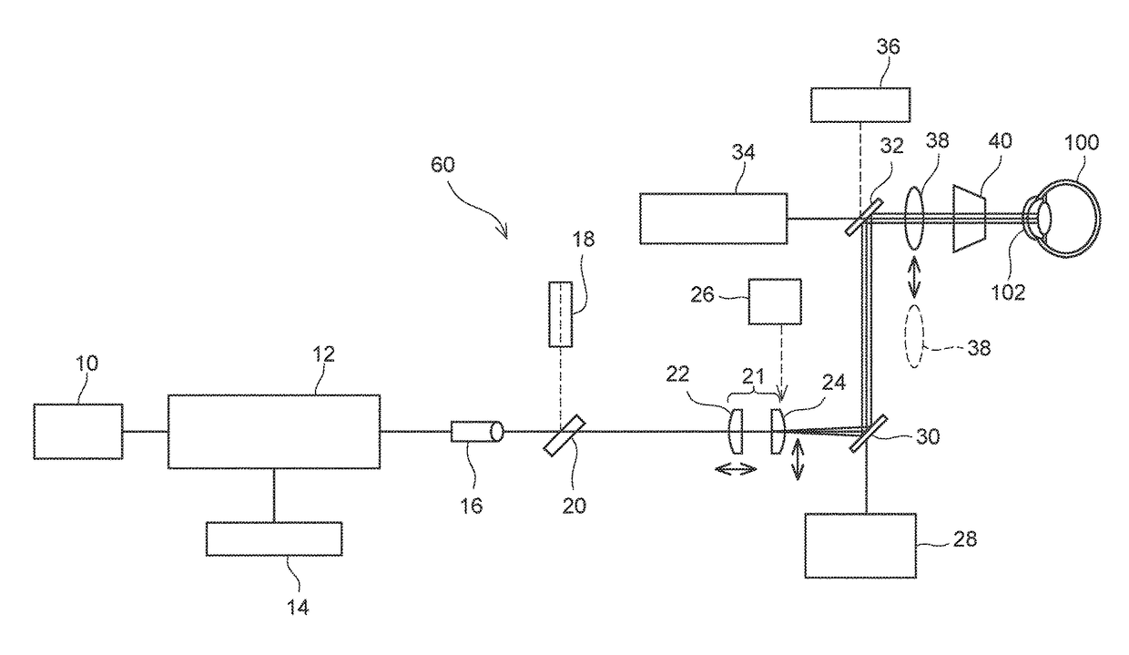
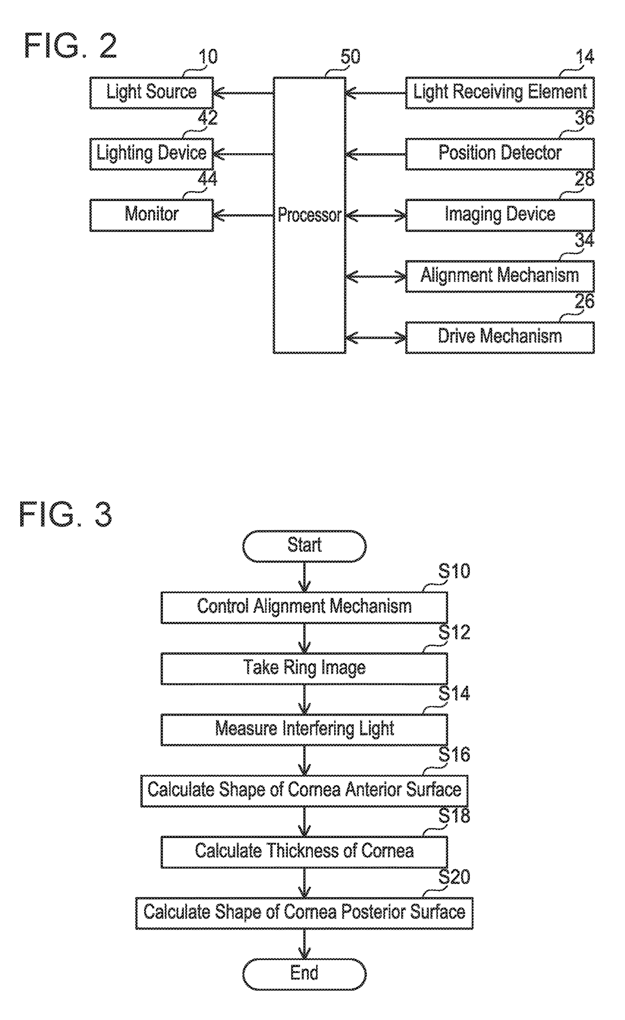
[0007]In the ophthalmological device, the shape of the cornea anterior surface of the eye to be examined is calculated based on the reflected images of the plurality of ring light obtained in the ring image photographic optical system. In addition, the thicknesses of the cornea at the plurality of incident positions are calculated based on the interfering light at the plurality of incident positions obtained in the interference optical system. Each position of the cornea posterior surface can be specified from the corresponding position of the cornea anterior surface and the thickness of the cornea at this position. Therefore, the processor calculates the shape of the cornea posterior surface using the position of the cornea posterior surface specified from the calculated shape of the cornea anterior surface and the calculated thicknesses of the cornea of the eye to be examined. The ophthalmological device enables measurement of the shape of the cornea posterior surface.

Problems solved by technology

Therefore, error in the estimated shape of the cornea posterior surface hinders proper prescription of the intraocular lens.

Method used


Image

  • Ophthalmological device
  • Ophthalmological device
  • Ophthalmological device

Examples


embodiment 1

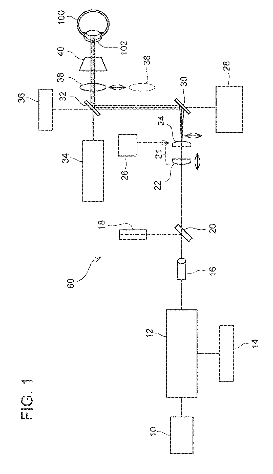
[0017]As shown in FIG. 1, the ophthalmological device of the present embodiment includes a measurement unit 60 for examining a cornea 102 of an eye to be examined 100. The measurement unit 60 includes: a ring image photographic optical system (28, 30, 32, 40) for measuring the shape of the anterior surface of the cornea 102; an interference optical system (10, 12, 14, 16, 18, 20, 22, 24, 30, 32, 36, 38) for measuring the thickness of the cornea 102; and an alignment mechanism 34 for aligning the measurement unit 60 in a predetermined positional relationship with respect to the eye to be examined 100.

[0018]The ring image photographic optical system (28, 30, 32, 40) radiates a plurality of concentric ring light to the anterior surface (front surface) of the cornea 102, and takes reflected images of the plurality of ring light reflected from the anterior surface of the cornea 102. The ring image photographic optical system includes a cone 40, a lighting device 42 (not shown in FIG. 1, ...


PUM


Abstract

An ophthalmological device calculates a cornea surface shape of an eye to be examined. The ophthalmological device includes a ring image photographic optical system configured to radiate a plurality of concentric ring light to the cornea surface of the eye and take reflected images of the plurality of ring light reflected from the cornea surface of the eye, an interference optical system configured to radiate measurement light to the eye and detect interfering light composed of reflected light of the measurement light reflected from the eye and predetermined reference light. The shape of the cornea anterior surface of the eye is calculated form the reflected images of the plurality of ring light, the thicknesses of the cornea of the eye at the plurality of incident positions is calculated from the interfering light, and the posterior surface shape of the cornea of the eye is calculated based on these two results.

Description

CROSS-REFERENCE TO RELATED APPLICATION[0001]This application claims priority to Japanese Patent Application No. 2015-015950 filed on Jan. 29, 2015, the entire contents of which are hereby incorporated by reference into the present application.TECHNICAL FIELD[0002]The present application is related to an ophthalmological device to examine an eye.BACKGROUND[0003]A treatment of implanting an intraocular lens (IOL) in a patient's eye may be conducted. For example, in a cataract surgery, after a crystalline lens is removed from inside the patient's eye, an intraocular lens (IOL) is inserted into the patient's eye. For determining the power of the intraocular lens, eye characteristics data such as the eye axial length and the cornea curvature (cornea refractivity) of the targeted eye are measured in advance, and based on the obtained eye characteristics data, the power of the intraocular lens is determined in accordance with a known IOL calculation formula. Particularly, in order to prope...

Claims


Application Information

Patent Timeline
Patent Type & Authority Patents(United States)
IPC IPC(8): A61B3/10A61B3/107A61B3/00A61B3/14
CPCA61B3/107A61B3/0025A61B3/102A61B3/1005A61B3/14A61B2560/06
Inventor KATO, CHIHIRONOZAWA, YUJIOKAMOTO, KEIICHIRO
Owner TOMEY CORP
Learn More