
Ophthalmic apparatus and a method for calculating internal eye refractive power distribution

a technology ophthalmic apparatus, which is applied in the field of ophthalmic apparatus for obtaining internal refractive power distribution of an eye, can solve the problem that the refractive power distribution of the crystalline lens cannot be estimated accurately, and achieve the effect of easy evaluation of refractive power distribution

Active Publication Date: 2006-02-09
NIDEK CO LTD
View PDF7 Cites 16 Cited by
  • Summary
  • Abstract
  • Description
  • Claims
  • Application Information

AI Technical Summary

Benefits of technology

[0005] An object of the invention is to overcome the problems described above and to provide an ophthalmic apparatus and a method for calculating internal refractive power distribution of an eye, which allow easily evaluating refractive power distribution of a crystalline lens, an intraocular lens and the like.

Problems solved by technology

However, in the case of an eye with keratoconus and an eye having its axis deviated (decentered) at the time of corneal refractive surgery, the refractive power distribution of the crystalline lens cannot be estimated accurately since a corneal posterior surface as well as a corneal surface of the eye with keratoconus, and a corneal surface of the eye with the deviated axis are widely distorted, and thereby a prism component (component of tilt) is included in the internal refractive power distribution.

Method used


Image

  • Ophthalmic apparatus and a method for calculating internal eye refractive power distribution
  • Ophthalmic apparatus and a method for calculating internal eye refractive power distribution
  • Ophthalmic apparatus and a method for calculating internal eye refractive power distribution

Examples


Embodiment Construction

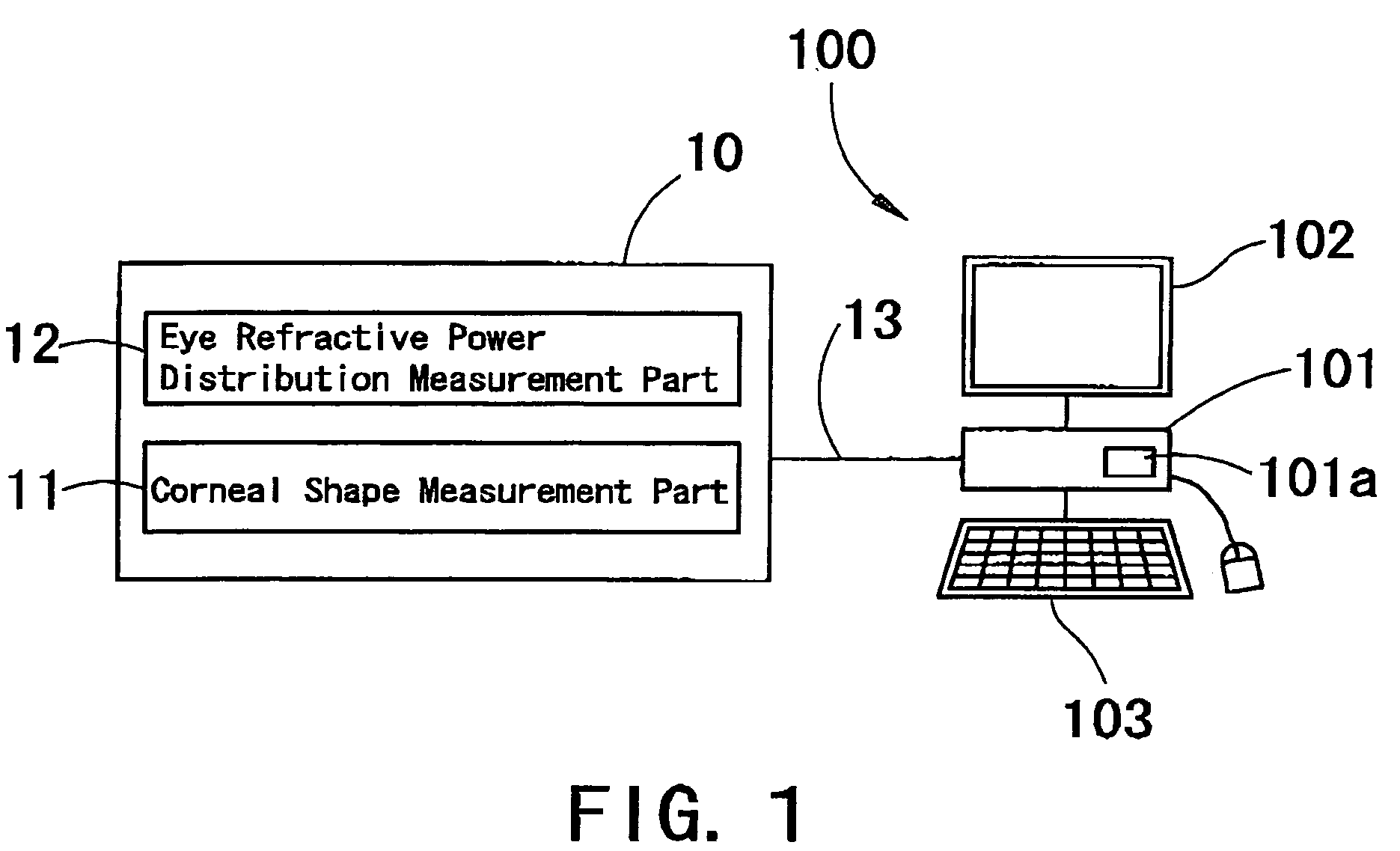
[0019] A detailed description of one preferred embodiment of an ophthalmic apparatus and a method for calculating internal refractive power distribution of an eye embodied by the present invention is provided below with reference to the accompanying drawings. FIG. 1 is a view showing a schematic configuration of an ophthalmic system for obtaining internal refractive power distribution of an eye. A measurement apparatus 10 includes a corneal shape measurement part 11 and an eye refractive power distribution measurement part 12. Respective measurement data on a corneal shape and eye refractive power distribution obtained by the measurement apparatus 10 is inputted into a computer 100 via a cable 13 or a recording media. The computer 100 includes a processor 101 equipped with a program for obtaining the internal refractive power distribution, a display 102, and an input device 103 such as a keyboard.

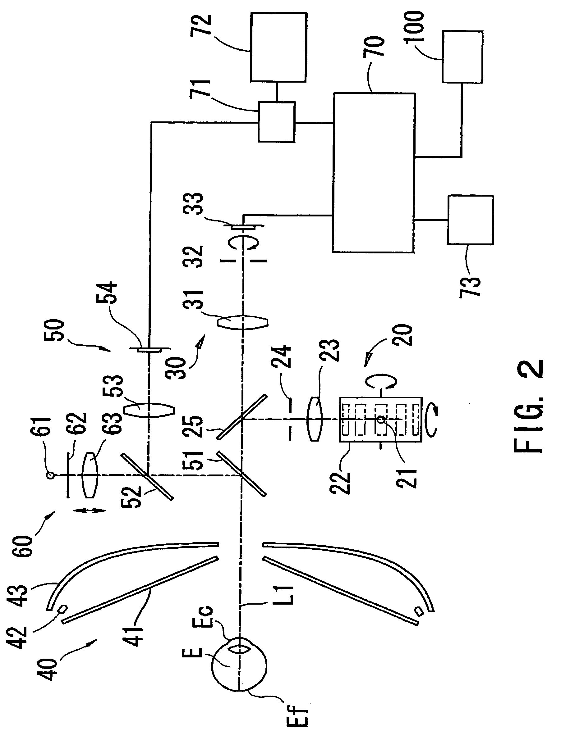
[0020]FIG. 2 is a view showing a schematic configuration of an optical system in the m...


PUM


Abstract

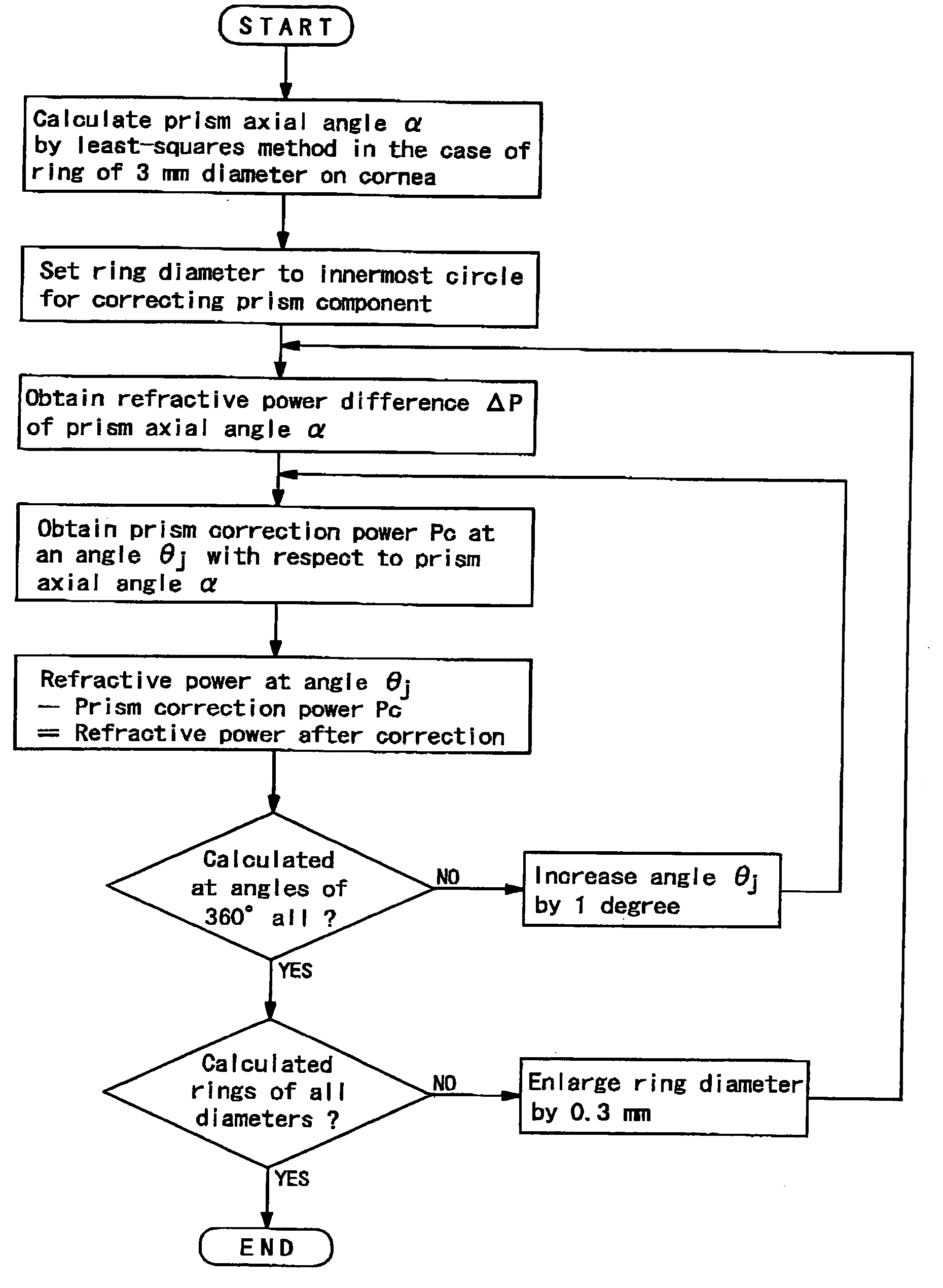
An ophthalmic apparatus and a method for calculating internal refractive power distribution of an eye of an examinee, which allow easily evaluating refractive power distribution of a crystalline lens, an intraocular lens and the like. The ophthalmic apparatus has a unit which inputs respective measurement data on corneal refractive power distribution and whole refractive power distribution of the eye, the respective distribution referring to a reference axis, and a unit which obtains the internal refractive power distribution of the eye referring to the reference axis based on the inputted respective measurement data, obtains a prism component in the internal refractive power distribution with respect to the reference axis, and obtains internal refractive power distribution of the eye where the prism component is removed.

Description

BACKGROUND OR THE INVENTION [0001] 1. Field of the Invention [0002] The present invention relates to an ophthalmic apparatus for obtaining internal refractive power distribution of an eye, and a method for calculating the same. [0003] 2. Description of Related Art [0004] Conventionally, an ophthalmic apparatus has been proposed which obtains internal (intraocular) refractive power distribution of an eye between a corneal posterior surface and a retina based on data on corneal refractive power distribution of the eye obtained by a corneal shape measurement apparatus or the like and data on whole refractive power distribution of the eye obtained by a wave front aberration measurement apparatus or an eye refractive power measurement apparatus, and displays the obtained internal refractive power distribution in a color-scaled map. With the use of this kind of apparatus, refractive power distribution of a crystalline lens, an intraocular lens implanted in the eye, and the like may be est...

Claims


Application Information

Patent Timeline
IPC IPC(8): A61B3/10A61B3/00
CPCA61B3/1015A61F2009/00872A61B3/107
Inventor FUJIEDA, MASANAOBAN, YUKINOBU
Owner NIDEK CO LTD
Learn More