Jumper clamps

a technology of clamping clamps and clamping rods, applied in the direction of electric connection bases, etc., can solve problems such as the failure of the clamping process, and achieve the effect of effective and efficient delivery and cutting current flow resistan

Active Publication Date: 2017-06-27
PARIS BUSINESS PRODS
View PDF13 Cites 13 Cited by
  • Summary
  • Abstract
  • Description
  • Claims
  • Application Information

AI Technical Summary

Benefits of technology

[0004]It is thus the object of the present invention to provide jumper clamps in a jumper clamp system that overcomes the limitations and disadvantages of prior jumper clamps and their systems. This object is accomplished by providing jumper clamps that receive electricity from a single electrical power source and effectively and efficiently deliver, to the battery or other device, twice the electricity through each jumper clamp than the electricity transmitted by prior jumper clamps, by cutting current flow resistance in half.

Problems solved by technology

Often times, however, the jumping process fails because it is unable to conduct sufficient electricity.
This may be due to the failure of the jumper clamps to deliver adequate electrical power, since prior clamps have excessive resistance to current flow.

Method used


Image

  • Jumper clamps
  • Jumper clamps
  • Jumper clamps

Examples


Embodiment Construction

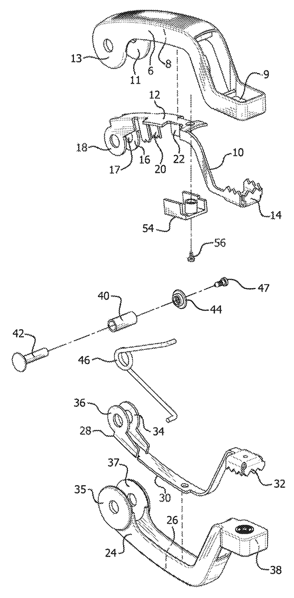
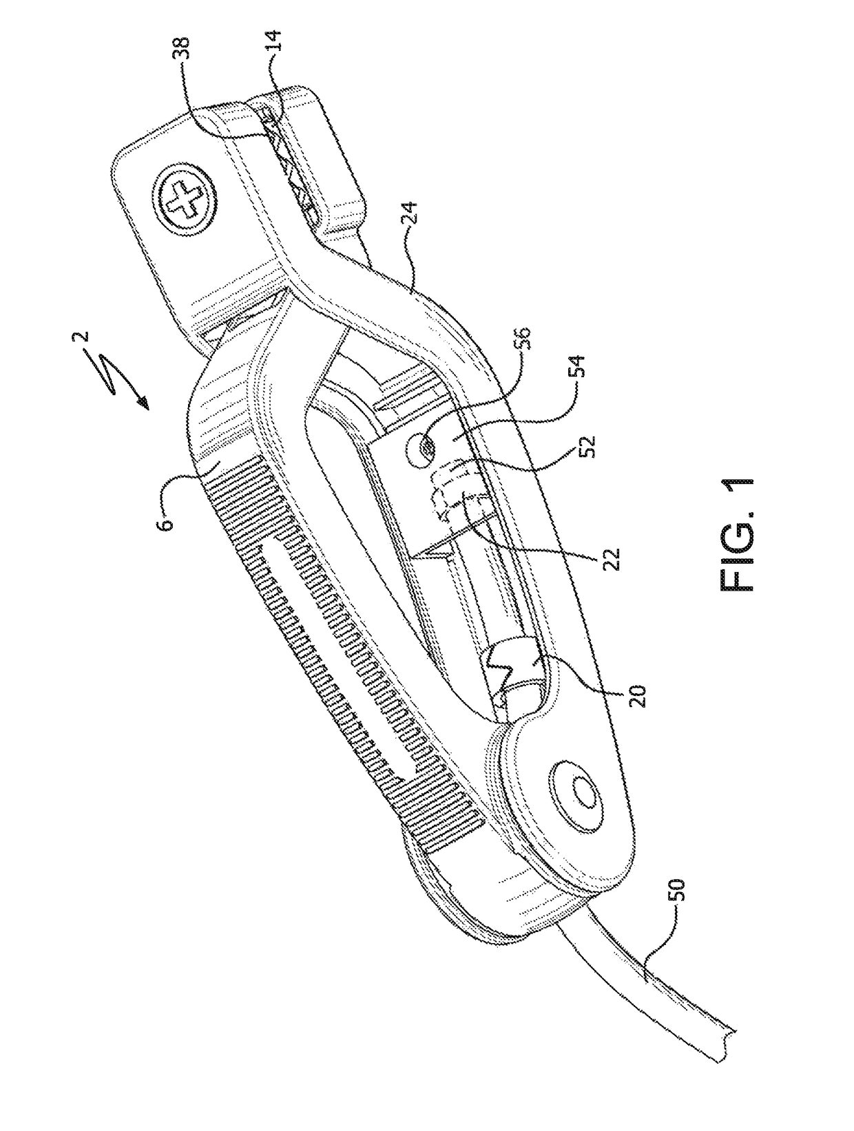
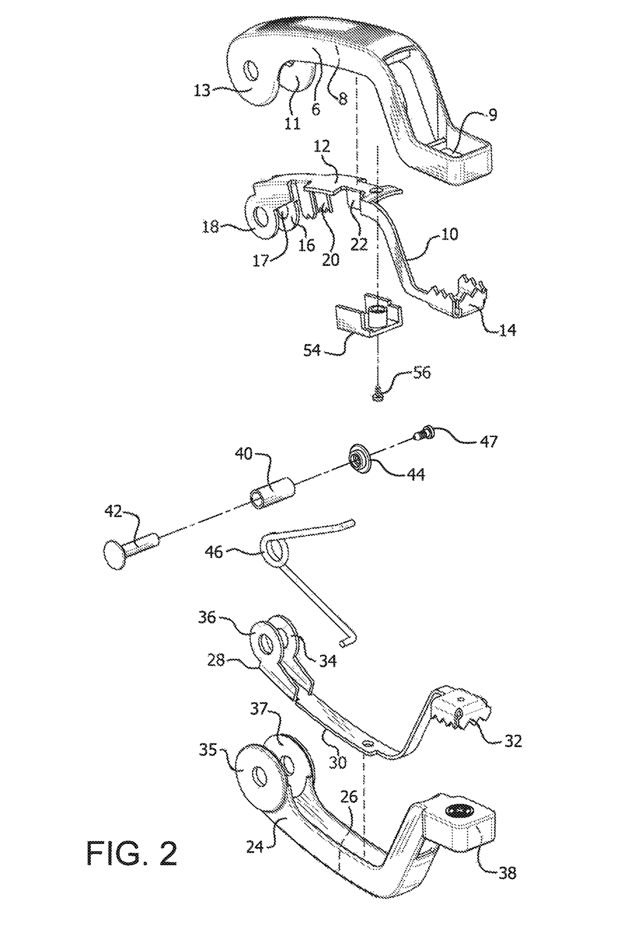
[0011]The jumper clamp system of the invention comprises jumper clamps 2 and 4. The clamps are identical, except that clamp 2 is identified as the clamp for use on battery 80 or other electrically rechargeable device having positive electrical terminal 60 and clamp 4 is identified for use on negative electrical terminal 70. Thus, the description and operation of clamp 2 which follows is thus applicable to substantially identical clamp 4 as well.

[0012]Clamp 2 comprises upper clamp frame 6 made of plastic or equivalent, non-electrical conductive material. Clamp frame 6 has internal recess 8 into which first electricity conductor means in the form of upper conductive contact plate 10 is positioned. Contact plate 10, made of an electricity conductive metal, is an integral, elongated member comprising top section 12, jaw member 14 at one end of the top section and dual discs 16 and 18 at the other end of the top section. Electrical conductive wire entry passage 17 is located between disc...


PUM


Abstract

A dual conductive electrical jumper clamp system has two jumper clamps, each jumper clamp having upper and lower clamp frames and an electrical conductive contact plate positioned within each frame. An electrical conductive sleeve is positioned between the contact plates. In this manner, electricity is transmitted from an electric power source to only one of the contact plates, then solely to the other contact plate via the conductive sleeve, and ultimately to electrical terminal attaching jaw members at the ends of the contact plates.

Description

RELATED APPLICATION[0001]This application claims the benefit of Application Ser. No. 62 / 206532, filed on Aug. 18, 2015.BACKGROUND OF THE INVENTION[0002]Jumper clamps, with their connecting electrical cables, are well known for use in charging low or dead batteries or other electrical devices which require a charge from a live electrical power source. Such jumper clamps routinely consist of interlocking jaw members configured to attach to the positive and negative electrical terminals of batteries and the like. Once connected to the terminals, electricity from the single power source is delivered to one of the jaw members of each clamp, which then transmits the electricity, through the terminals, to jump the battery.[0003]Often times, however, the jumping process fails because it is unable to conduct sufficient electricity. This may be due to the failure of the jumper clamps to deliver adequate electrical power, since prior clamps have excessive resistance to current flow.SUMMARY OF ...

Claims


Application Information

Patent Timeline
Patent Type & Authority Patents(United States)
IPC IPC(8): H01R11/24
CPCH01R11/24
Inventor TOSCANI, GERARD MMACK, JR., HENRY J.SHA, OLIVER
Owner PARIS BUSINESS PRODS
Why Eureka
Try Eureka