Body part treatment device with air diverter

Inactive Publication Date: 2007-11-22
BROOKSTONE PURCHASING
View PDF16 Cites 10 Cited by
  • Summary
  • Abstract
  • Description
  • Claims
  • Application Information

AI Technical Summary

Benefits of technology

[0007]It has been discovered that massaging devices, such as the foot massager described previously, often do not effectively or efficiently deliver air from the air blower to the treatment area. Acco

Problems solved by technology

It has been discovered that massaging devices, such as the foot massager described previously,

Method used


Image

  • Body part treatment device with air diverter
  • Body part treatment device with air diverter
  • Body part treatment device with air diverter

Examples


Embodiment Construction

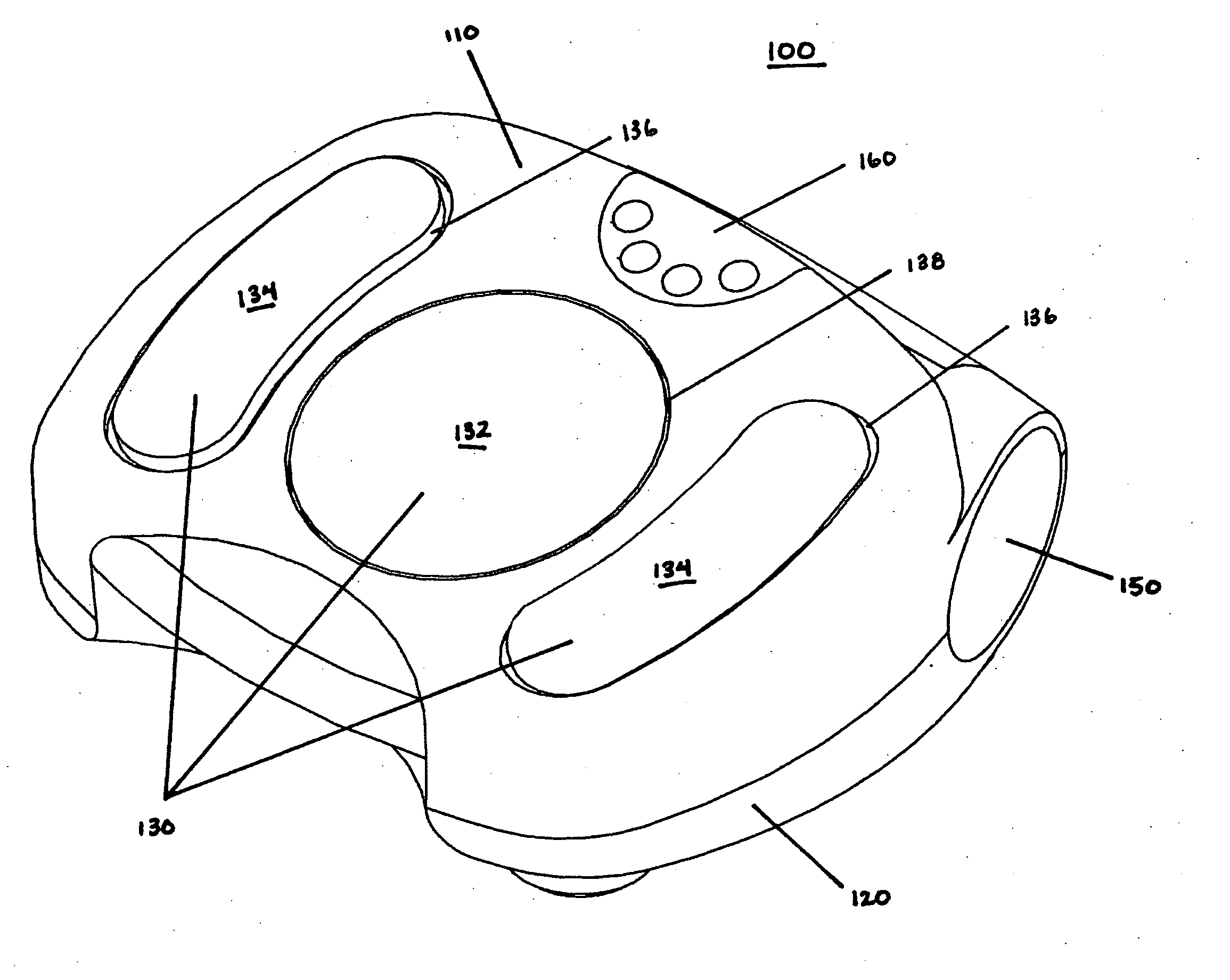
[0017]It has been discovered that treatment devices, such as massaging devices, that also therapeutically apply air from an air blower do not effectively or efficiently deliver the air to the treatment areas. In many cases, the size, shape, positioning, and orientation of the air blower within the massager housing is affected by other components of the massaging device or by the desire to have a compact or aesthetically pleasing housing design. Thus, delivery of heated air to the treatment areas is far less than optimal. Accordingly, the present invention provides a treatment device with an air diverter that promotes effective and efficient delivery of air from an air blower to the treatment areas of the treatment device, regardless of the size, shape, positioning, or orientation of the air blower in the treatment device.

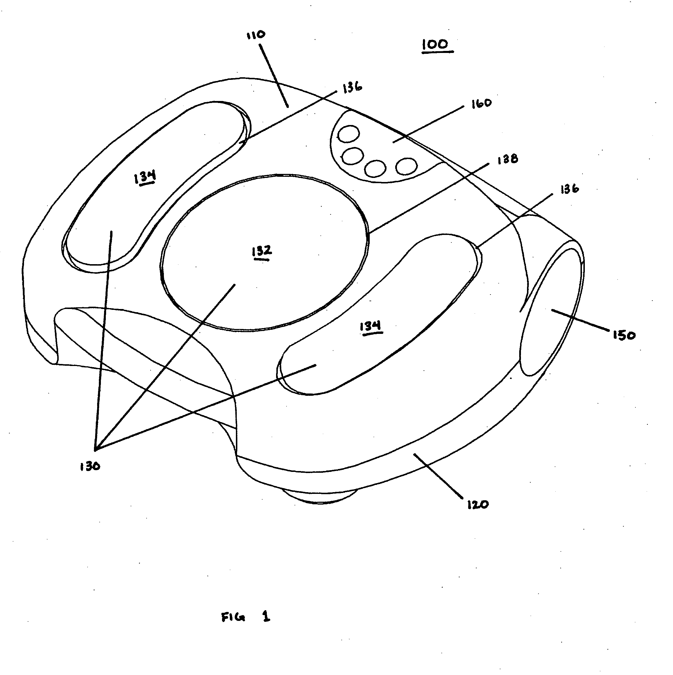
[0018]As illustrated in FIG. 1, an exemplary embodiment of the present invention is a foot massaging device 100 with a first, or upper, housing 110 and a second, or...


PUM


Abstract

A device for applying treatment, or therapy, to a body part directs air efficiently and effectively to the body part by using an air diverter. In particular, a device for treating a body part, such as a massager, has one or more treatment areas positioned to deliver treatment to the body part and an air blower having an air outlet that creates a flow of air in an outward direction from the air outlet. The air diverter is positioned to divert the flow of air to the one or more treatment areas.

Description

BACKGROUND OF THE INVENTION[0001]1. Field of the Invention[0002]The present invention relates generally to devices for applying treatment, or therapy, to a body part, and more particularly, to a device that treats a body part by directing air to the body part with an air diverter.[0003]2. Description of the Related Art[0004]Massage treatment or therapy involves the rubbing and kneading of the body's soft tissues, such as the skin and muscles. Massage may be helpful in reducing tension and pain, improving blood flow, and encouraging relaxation. In particular, massage stimulates blood circulation to improve the supply of oxygen and nutrients to body tissues, thereby easing tense and knotted muscles as well as stiff joints. To improve the beneficial effects created by massaging a soft tissue, some form of heating or cooling treatment may also be applied to the tissue area.[0005]Devices are available for self-application of massage therapy to an individual's own body. In order to create...

Claims


Application Information

Patent Timeline
IPC IPC(8): A62B9/02
CPCA61H2205/12A61H23/00
Inventor HARRIS, DAVIDMILLS, STEPHEN B.BUROUT, CHARLES J.
Owner BROOKSTONE PURCHASING
Why Eureka
Try Eureka