Protective structure, socket, plug and method assuring a live wire and a neutral wire to be powered off simultaneously when overheating

a technology of protection structure and neutral wire, which is applied in the direction of heating/cooling contact switches, thermal switch details, coupling device connections, etc., can solve the problems of destructing the fixing plate between the neutral wire spring plate and the neutral wire conductive plate, and the operator may get an electric shock

Inactive Publication Date: 2017-07-04
GREEN IDEA TECH INC
View PDF9 Cites 0 Cited by
  • Summary
  • Abstract
  • Description
  • Claims
  • Application Information

AI Technical Summary

Benefits of technology

[0019]The present invention also discloses a method which assures the live wire and the neutral wire to be powered off simultaneously when overheating. The method includes abutting the first limiting element and the second limiting element at the live wire spring plate and the neutral wire spring plate respectively, and using the connecting element to connect with the first limiting element and the second limiting element, allowing the connecting element to limit the live wire spring plate and the neutral wire spring plate, so that under a normal condition, the live wire spring plate and the live wire conductive plate can contact with each other, as well as the neutral wire spring plate and the neutral wire conductive plate can contact with each other; and selecting a thermal destructive material for the first limiting element, the second limiting element or the connecting element, with that the thermal destructive material is allowed to be destructed at a temperature of 80° C.-299° C., so that when a location between the live wire spring plate and the live wire conductive plate is overheated or a location between the neutral wire spring plate and the neutral wire conductive plate is overheated, if any one location in the first limiting element, the second limiting element or the connecting element is destructed, then the first limiting element, the second limiting element and the connecting element will all lose the original limiting function thereof, allowing the live wire spring plate, the live wire conductive plate, the neutral wire spring plate and the neutral wire conductive plate to be separated apart at a same time.

Problems solved by technology

If the location of overheating is between the neutral wire spring plate and the neutral wire conductive plate, then the fixing plate between the neutral wire spring plate and the neutral wire conductive plate will be destructed due to overheating.
Therefore, the high electric current can still enter into the load prior to forming an open circuit; whereas, if electricity leaks out of the load and an operator touches the load under grounding, then the operator may get an electric shock.

Method used


Image

  • Protective structure, socket, plug and method assuring a live wire and a neutral wire to be powered off simultaneously when overheating
  • Protective structure, socket, plug and method assuring a live wire and a neutral wire to be powered off simultaneously when overheating
  • Protective structure, socket, plug and method assuring a live wire and a neutral wire to be powered off simultaneously when overheating

Examples


first embodiment

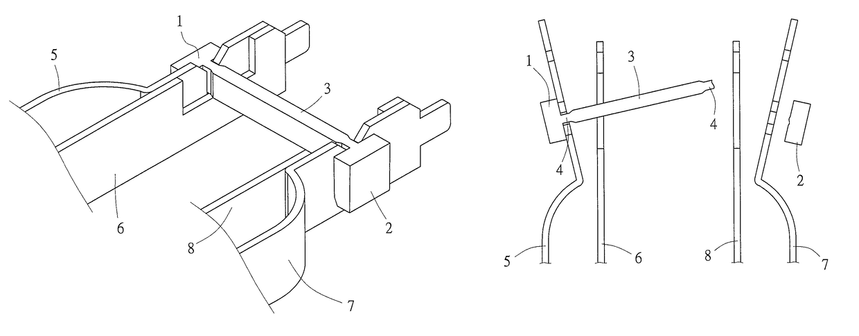
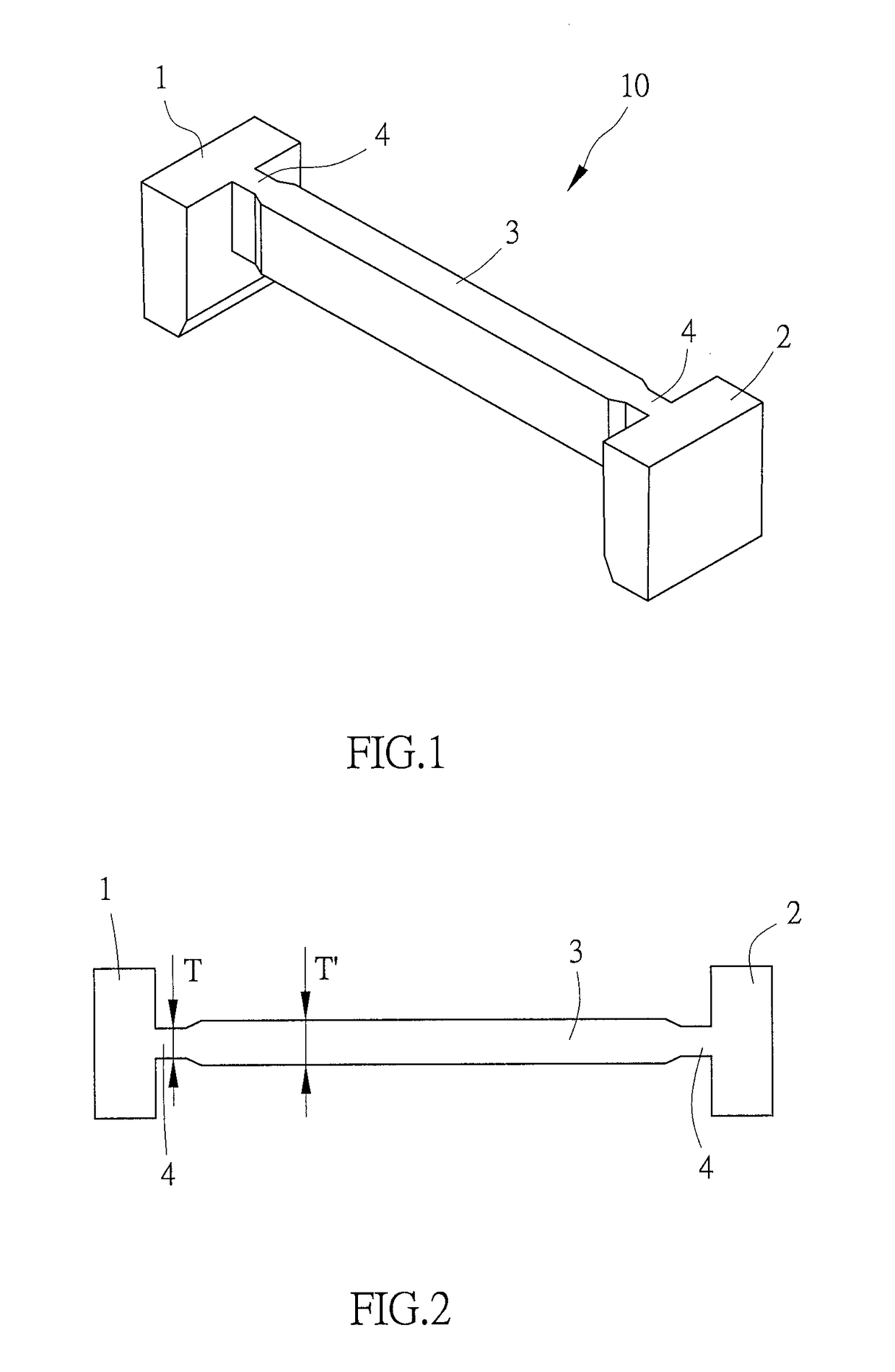
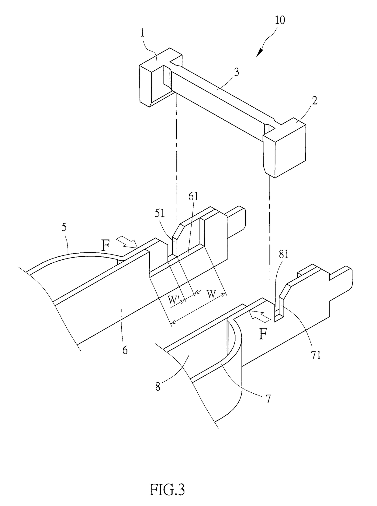
[0050]Referring to FIG. 1 and FIG. 2 for the present invention, the protective structure 10 assuring the live wire and the neutral wire to be powered off simultaneously when overheating, according to the present embodiment, comprises a first limiting element 1, a second limiting element 2 and a connecting element 3. The connecting element 3 is connected with the first limiting element 1 and the second limiting element 2, forming an H-shaped structure to the protective structure 10 that assures the live wire and the neutral wire to be powered off simultaneously when overheating. The first limiting element 1, the second limiting element 2 and the connecting element 3 are selectively made of a thermal destructive material, such as plastic. The thermal destructive material is allowed to be destructed at a temperature of 80° C.-299° C., and the first limiting element 1 and the second limiting element 2 are in a plate shape. A destructive portion 4 is disposed between the connecting eleme...

second embodiment

[0053]Referring to FIG. 6 for the present invention, the protective structure 10A assuring the live wire and the neutral wire to be powered off simultaneously when overheating, according to the present embodiment, comprises a first limiting element 1A, a second limiting element 2A and a connecting element 3A. The connecting element 3A is connected with the first limiting element 1A and the second limiting element 2A, forming an H-shaped structure to the protective structure 10A that assures the live wire and the neutral wire to be powered off simultaneously when overheating. The first limiting element 1A and the second limiting element 2A are made of metal, and the connecting element 3A is made of plastic. A destructive portion 4A is disposed between the connecting element 3A and the first limiting element 1A as well as between the connecting element 3A and the second limiting element 2A. In the present embodiment, heat can be transferred more uniformly and rapidly by the first limi...

third embodiment

[0054]Referring to FIG. 7 for the present invention, the protective structure 10B assuring the live wire and the neutral wire to be powered off simultaneously when overheating, according to the present embodiment, comprises a first limiting element 1B, a second limiting element 2B and a connecting element 3B. The connecting element 3B is connected with the first limiting element 1B and the second limiting element 2B, the first limiting element 1B is formed with a first collar 11B and the second limiting element 2B is formed with a second collar 21B. In addition, part of the wall of the first collar 11B is thinner to form a first destructive portion 12B, and part of the wall of the second collar 21B is thinner to form a second destructive portion 22B.

[0055]Referring to FIG. 8 and FIG. 9, there are a live wire spring plate 5B, a live wire conductive plate 6B, a neutral wire spring plate 7B and a neutral wire conductive plate 8B. An external force F is applied first to abut the live wi...


PUM


Abstract

The present invention discloses a protective structure, plug, socket and method assuring a live wire and a neutral wire to be powered off simultaneously when overheating. The present invention limits a live wire spring plate from contacting with a live wire conductive plate, and a neutral wire spring plate from contacting with a neutral wire conductive plate, such that when the live wire spring plate and the live wire conductive plate are overheated or the neutral wire spring plate and the neutral wire conductive plate are overheated, the live wire spring plate, the live wire conductive plate, the neutral wire spring plate and the neutral wire conductive plate can be separated apart at a same time.

Description

BACKGROUND OF THE INVENTION[0001]a) Field of the Invention[0002]The present invention relates to a protective structure, socket, plug and method assuring a live wire and a neutral wire to be powered off simultaneously when overheating, and more particularly to an invention wherein when a live wire spring plate and a live wire conductive plate are overheated or a neutral wire spring plate and a neutral wire conductive plate are overheated, the live wire spring plate, the live wire conductive plate, the neutral wire spring plate and the neutral wire conductive plate are assured to be separated apart at a same time.[0003]b) Description of the Prior Art[0004]To prevent a circuit from issues of current overload, short circuit and overheating, a fuse or an overload protector is usually provided at the circuit. When the temperature of the circuit gets too high or the current gets too large, the fuse affected by the high temperature becomes blown or a bi-metal shrapnel of the overload prote...

Claims


Application Information

Patent Timeline
Patent Type & Authority Patents(United States)
IPC IPC(8): H01R13/68H01H37/76H01H37/32H01R13/713H01T1/14H01T4/06G08B17/06H01H37/00
CPCH01H37/76H01R13/7137H01H37/32H01T1/14H01T4/06H01H37/765H01H37/002G08B17/06H01H37/764H01H71/002H01H71/20
Inventor I, HSIANG-YUN
Owner GREEN IDEA TECH INC
Why Eureka
Try Eureka