Joining a workpiece in a concealed joining seam

a technology of concealed joining seam and workpiece, which is applied in the direction of instrumentation, programme control, auxiliary welding devices, etc., can solve the problems of increasing costs, prolonging cycle time in production lines, and adding additional process steps

Active Publication Date: 2017-07-11
FFT PRODIONSSYST
View PDF9 Cites 69 Cited by
  • Summary
  • Abstract
  • Description
  • Claims
  • Application Information

AI Technical Summary

Benefits of technology

[0007]There is therefore a need for a method using which it is possible to detect a position of a concealed joining contour before beginning the joining process, without having to gauge the workpieces in a complicated and / or costly way.
[0018]In order to obtain as exact a position as possible, the controller can comprise a filter algorithm which processes the value(s) of the parameter(s) detected by the detector, in order to at least partially eliminate known distortions in the data captured.
[0037]In order to produce the exploratory seam and the joining seam, a beam-emitting part of a system which produces the high-energy beam and / or the detector of the quality control device can be affixed to a robot arm and form a combined joining and control tool. The robot arm can be able to be freely moved spatially.
[0041]A computer can feature: a digital microprocessor unit (CPU) with a data connection to a storage system and a bus system; a working memory (RAM); and a storage means. The CPU is designed to: implement commands which are embodied as a program which is stored in a storage system; detect input signals from the data bus; and emit output signals to the data bus. The storage system can feature various storage media such as optical, magnetic, solid-state and other non-volatile media, on which a corresponding computer program for performing the method and the advantageous embodiments is stored. The program can be designed such that it represents and / or is capable of performing the methods described here, such that the CPU can perform the steps of such methods and can therefore control the energy beam of the joining device.

Problems solved by technology

This additional process step takes time and therefore increases costs.
Gauging and aligning each workpiece is time-consuming and can therefore for example prolong a cycle time in a production line.
This prolonged cycle time leads to a lower throughput per unit time and therefore increases costs.

Method used


Image

  • Joining a workpiece in a concealed joining seam
  • Joining a workpiece in a concealed joining seam
  • Joining a workpiece in a concealed joining seam

Examples


Embodiment Construction

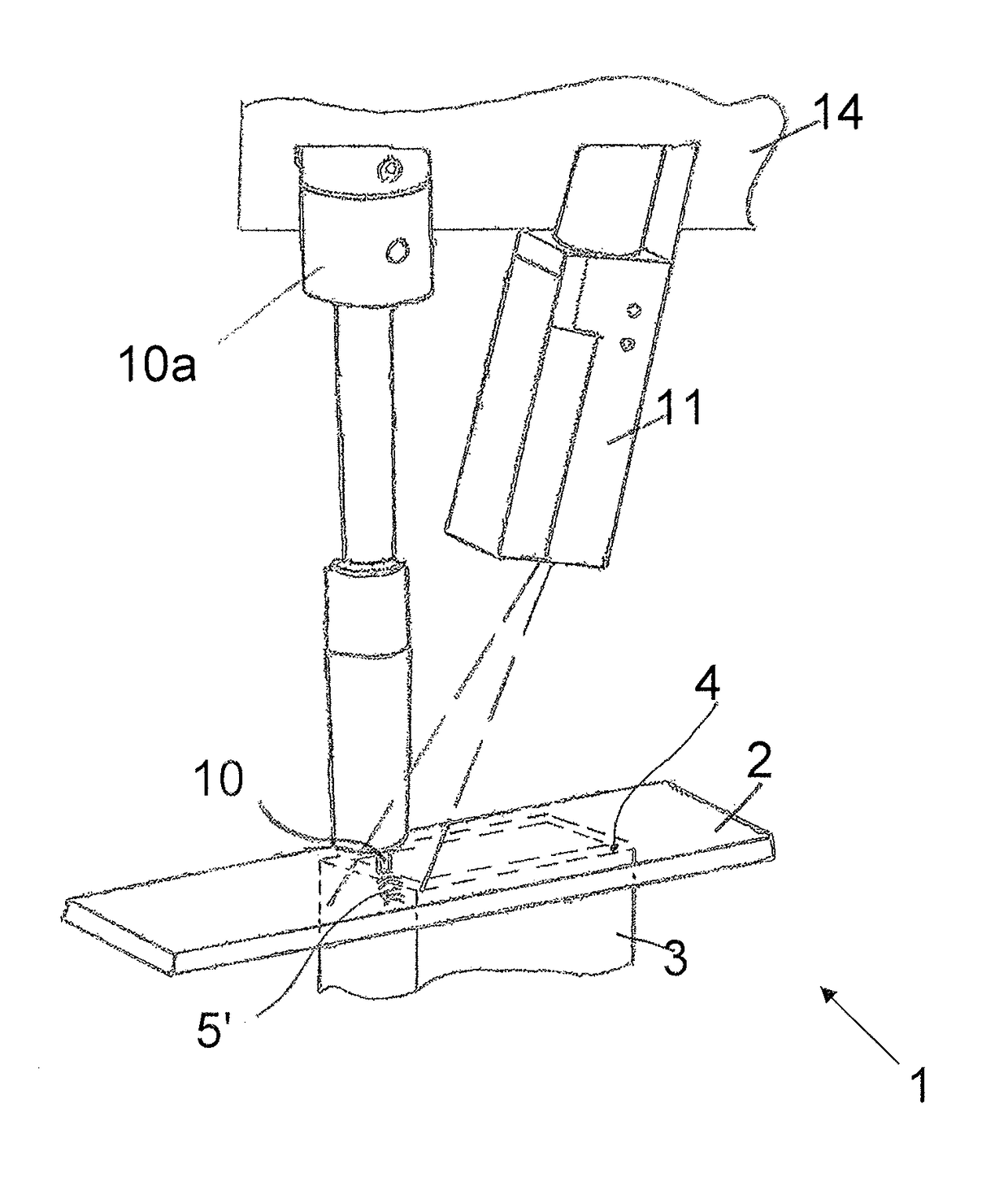
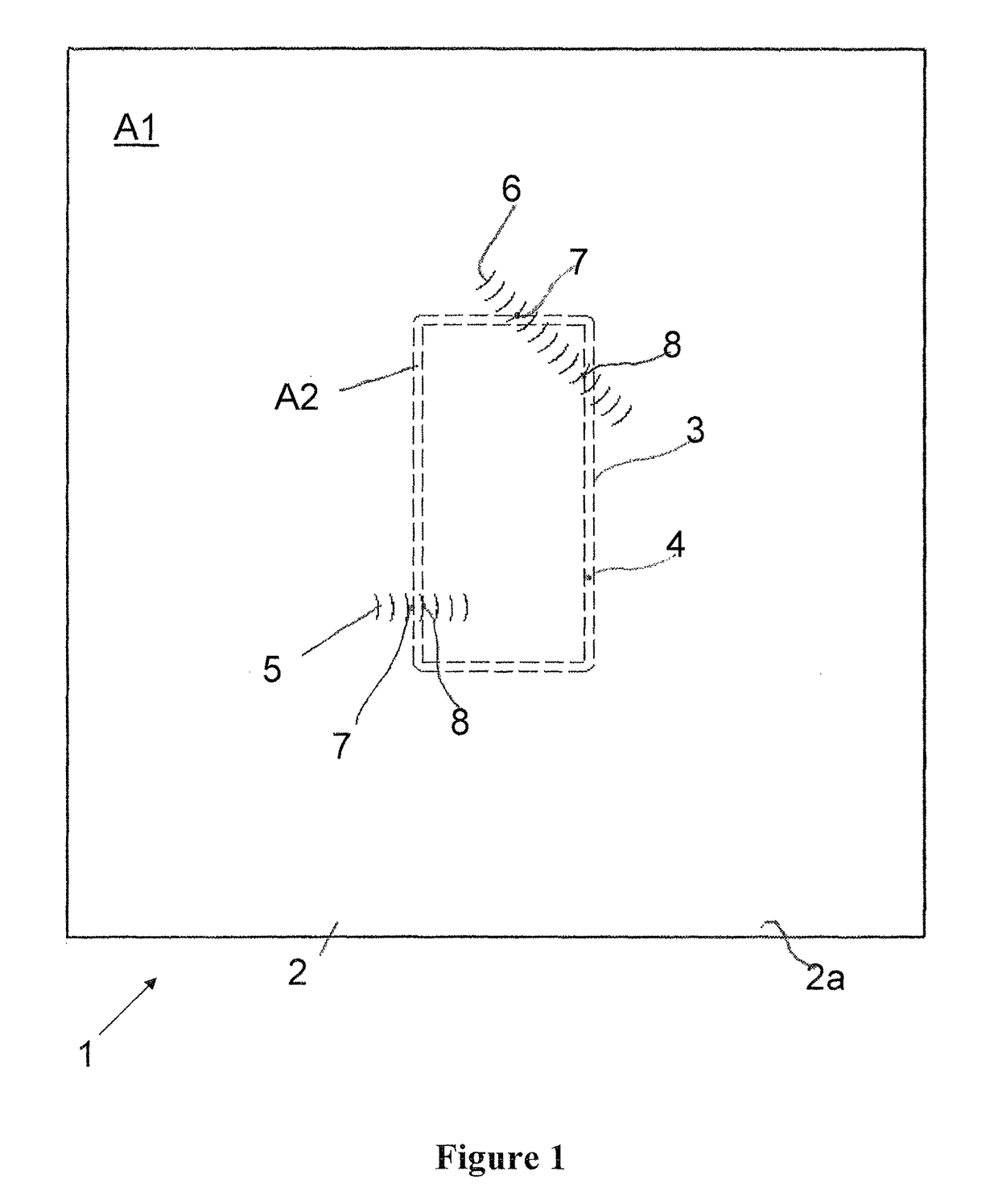
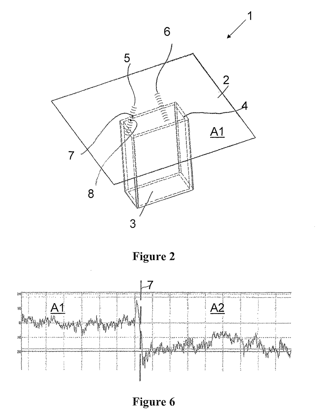
[0054]FIG. 1 shows a workpiece 1 consisting of an upper workpiece part 2 and a lower workpiece part 3. The upper workpiece part 2 lies on the lower workpiece part 3, such that an energy beam 10 shown in FIG. 4 cannot directly process the joining contour 4 along which the upper workpiece part 2 contacts the lower workpiece part 3.

[0055]In order to be able to determine an exact position of the lower workpiece part 3 relative to the upper workpiece part 2, two exploratory seams 5, 6 have been produced—in the example embodiment, by means of the energy beam 10—on an upper side 2a of the upper workpiece part 2 which faces the energy beam 10.

[0056]Since the approximate position of the lower workpiece part 3 relative to the upper workpiece part 2 is known with regard to general joining tolerances, the energy beam 10 can place the beginning of the exploratory seam 5; 6 on the upper side 2a of the upper workpiece part 2 in an area which already lies near the joining contour 4, wherein the exp...


PUM

PropertyMeasurementUnit
energyaaaaaaaaaa
surface areaaaaaaaaaaa
temperatureaaaaaaaaaa

Abstract

A method for joining concealed workpiece parts by an energy beam, wherein a lower workpiece part and an upper workpiece part are positioned relative to each other; the upper workpiece part contacts the lower workpiece part along a joining contour; the energy beam is directed onto an upper side of the upper workpiece part, moved along the joining contour by a controller, in order to join the upper workpiece part to the joining contour; an exploratory seam is produced on the upper work piece part, for detecting the joining contour; a detector detects a boundary at which a surface area of the upper work piece part borders a surface area of the upper work piece part which does have contact with the joining contour; the controller registers a position of the boundary and compares it with a target position of the boundary which is stored in the controller.

Description

CROSS REFERENCE TO RELATED APPLICATIONS[0001]This application is the U.S. National Phase Application of PCT / EP2014 / 059929, filed May 15, 2014, which claims priority to European Patent Application No. 13168793.1, filed May 22, 2013, the contents of such applications being incorporated by reference herein.FIELD OF THE INVENTION[0002]The invention relates to a method for joining concealed workpiece parts by means of an energy beam.BACKGROUND OF THE INVENTION[0003]A joining technique is known in which two parts are to be joined to each other in an area in which one part is lying on the other, such that the joining seam for connecting the two parts has to be produced through the part lying on top, wherein the relative position of the two parts with respect to each other is usually determined by gauging the parts and gauging the positions of the two parts relative to each other in the joining position.[0004]Once the two parts are calibrated in their joining position in the joining station...

Claims


Application Information

Patent Timeline
Patent Type & Authority Patents(United States)
IPC IPC(8): B23K37/04B23K13/02B23K26/28B23K26/042B23K10/02B23K9/028B23K26/08B25J9/16B23K26/244B23K37/047B23K37/02B23K101/00
CPCB23K37/04B23K9/028B23K10/02B23K13/02B23K26/042B23K26/0884B23K26/244B23K26/28B23K37/0258B23K37/047B23K37/0452B25J9/1684B25J9/1694B23K2201/006G05B2219/37431G05B2219/45104G05B2219/4704G05B2219/4705G05B2219/4706B23K2101/006
Inventor KRAFT, MARTINSCHNEEGANS, JOCHEN
Owner FFT PRODIONSSYST
Why Eureka
Try Eureka