Gas injector having a dual valve needle

a gas injector and dual-valve technology, which is applied in the direction of engines, mechanical equipment, machines/engines, etc., can solve the problems of often inability to realize large flow cross-sections, and achieve the effect of compact and small design and compact design

Active Publication Date: 2017-07-11
ROBERT BOSCH GMBH
View PDF6 Cites 0 Cited by
  • Summary
  • Abstract
  • Description
  • Claims
  • Application Information

AI Technical Summary

Benefits of technology

[0006]In contrast, the gas injector according to the present invention for the injection of gaseous fuel for an internal combustion engine has the advantage that a flow cross-section in an open injector is able to be increased, so that even at low system pressures a sufficiently large gas quantity is injectable within a predefined time. The gas injector according to the present invention has a very compact and small design, so that it can be used even in tight engine compartments. The gas injector according to the present invention includes a valve body and a dual valve needle having an outer needle and an inner needle. In addition, an actuator system is provided, which is designed to actuate the outer needle and the inner needle independently of each other in each case. In the present invention, it is therefore possible to actuate only the outer needle or only the inner needle or both needles at different times. The largest opening cross-section preferably results when both needles are actuated. The outer needle is a hollow needle, and the inner needle is situated in the hollow region of the hollow outer needle. Furthermore, a first sealing seat is developed between the valve body and the outer needle, and a second sealing seat is developed between the outer needle and the inner needle. Placing the inner needle within the outer needle makes for a very compact design. If both needles are in the open state, a large opening cross-section can be achieved, and the required gas quantity or gas mass is able to be injected within a predefined period of time even at the lowest possible system pressure.
[0008]According to an alternative development of the present invention, the actuator system includes precisely one actuator, a first compression element and a second compression element. The first compression element is preferably situated between the inner needle and the outer needle, and the second compression element is preferably situated between the outer needle and the valve body. This configuration thus makes it possible to also realize a stepped opening of the inner needle and outer needle using precisely one actuator, preferably by selecting different prestress forces of the compression elements. The opening characteristic is therefore obtainable as a function of a lift effected by an actuator.
[0010]Moreover, the gas injector preferably includes a stop, which delimits a movement of the inner needle and / or the outer needle, so that a maximum lift can be specified in an uncomplicated manner. In particular when using two actuators for the individual actuation of the inner needle and the outer needle, the use of a stop makes it easy to restrict a maximum lift.

Problems solved by technology

However, the known injectors are only conditionally suitable for these gaseous fuels, since gaseous fuels have different energy densities and volumes than liquid fuels.
When configuring gas injectors, there is a conflict in objectives between the necessary mass flow rate during an injection and the need for the lowest possible system pressure of the gas.
However, because space is usually limited, the large flow cross-sections are frequently unable to be realized by simple upscaling of the dimensions of the injectors, especially in the case of outwardly opening injectors.

Method used


Image

  • Gas injector having a dual valve needle
  • Gas injector having a dual valve needle
  • Gas injector having a dual valve needle

Examples


Embodiment Construction

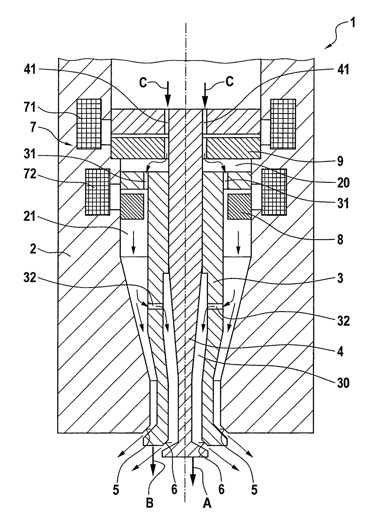
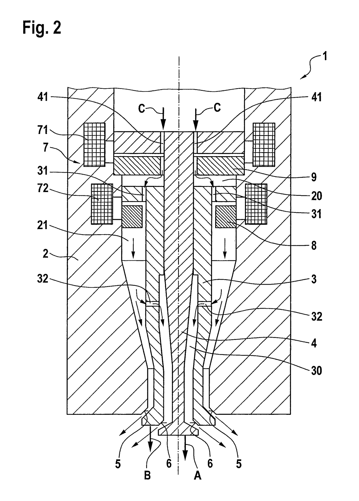
[0020]In the following text, a gas injector 1 according to a first preferred exemplary embodiment of the present invention is described in detail with reference to FIG. 2.

[0021]As can be gathered from FIG. 2, gas injector 1 includes a valve body 2 and a needle system which includes an outer needle 3 and an inner needle 4. Inner needle 4 is situated in a hollow region 30 of outer needle 3.

[0022]Moreover, gas injector 1 includes an actuator system 7 having a first actuator 71 and a second actuator 72. First actuator 71 actuates inner needle 4, and second actuator 72 actuates outer needle 3. Inner needle 4 is guided inside outer needle 3.

[0023]Moreover, a first sealing seat 5 is developed between outer needle 3 and valve body 2. In addition, a second sealing seat 6 is formed between inner needle 4 and outer needle 3. The two sealing seats are developed as circles. Outer needle 3 and inner needle 4 are both provided as outwardly opening needles, so that gas injector 1 is an outwardly op...


PUM


Abstract

A gas injector for injecting gaseous fuel includes: a valve body; an outer needle which is a hollow needle; an inner needle disposed in a hollow region of the outer needle; and an actuator system configured to actuate the outer needle and the inner needle independently of each other in each case. A first sealing seat is provided between the valve body and the outer needle, and a second sealing seat is provided between the outer needle and the inner needle.

Description

BACKGROUND OF THE INVENTION[0001]1. Field of the Invention[0002]The present invention relates to a gas injector for injecting gaseous fuel with the aid of a dual valve needle.[0003]2. Description of the Related Art[0004]Apart from liquid fuels, gaseous fuels, such as natural gas or hydrogen, have lately also been used for operating vehicles to an increasing extent. However, the known injectors are only conditionally suitable for these gaseous fuels, since gaseous fuels have different energy densities and volumes than liquid fuels. To ensure that internal combustion engines operated on the basis of such fuels have no excessive consumption and expel only a minimum of pollutants, it is necessary to inject the most exact gas quantities possible during each injection process. One or more injection process(es) per combustion cycle must also be possible in this context. Apart from the necessity of injecting a certain maximum quantity within a predefined period of time, there must also be t...

Claims


Application Information

Patent Timeline
Patent Type & Authority Patents(United States)
IPC IPC(8): F02M45/08F02M63/00F02M21/02F02M61/18F02M51/06
CPCF02M45/086F02M21/0254F02M21/0269F02M21/0275F02M51/061F02M61/1886F02M63/0007F02M51/0603Y02T10/32Y02T10/30
Inventor JAEGLE, FELIXOHLHAFER, OLAFSCHOEFER, JOERGGIEZENDANNER-THOBEN, ROBERT
Owner ROBERT BOSCH GMBH
Why Eureka
Try Eureka