Damping valve arrangement for a semiactive vibration damper

a semi-active and damper technology, applied in the direction of shock absorbers, thin material handling, servomotors, etc., can solve the problems of breakaway forces, system inertia, impede the rapid regulating movement,

Active Publication Date: 2016-06-14
KTM COMPONENTS GMBH
View PDF6 Cites 2 Cited by
  • Summary
  • Abstract
  • Description
  • Claims
  • Application Information

AI Technical Summary

Benefits of technology

[0036]According to another aspect of the invention, it is provided that the spring washers guide the armature radially and axially in the housing, and keep it at a distance from the inner circumferential wall of the housing, that is to say at a distance from the bore for accommodating the armature in the housing. This distance may be reduced due to the precise radial and axial guidance of the armature by the spring washers, thereby increasing the magnetic forces, which in turn is helpful in keeping the design of the damping valve arrangement very compact and small.
[0048]The invention also provides a method for controlling a pilot pressure in a control chamber of a damping device in a vibration damper. The process is realized by means of a magnetically actuated armature of a valve arrangement that changes the area of a flow-through opening in the valve arrangement through which a control fluid is able to flow. A spring washer, preferably coupled with the armature, is displaced relative to an encircling collar by means of the armature and the area of the flow-through opening between the spring washer and the collar is thus modified, and the spring washer guides the armature radially and axially relative to a housing that accommodates the armature.
[0040]In this context, the spring washers may advantageously have three cutouts, which results in the creation of three connecting crosspieces between a circumferential inner area and a circumferential outer area of the respective spring washers, each crosspiece being of wide design, affording high radial rigidity.
[0046]According to a refinement of the invention, it is further provided that the guide pin may be braced against the effect of the spring washers by means of (for example) a manually operable spring device; this functions in such manner that the flow-through opening is opened under predefined conditions, so that on the one hand the armature may be braced securely into a fail-safe position, and on the other hand volume production tolerances may be compensated.
[0048]The invention also provides a method for controlling a pilot pressure in a control chamber of a damping device in a vibration damper. The process is realized by means of a magnetically actuated armature of a valve arrangement that changes the area of a flow-through opening in the valve arrangement through which a control fluid is able to flow. A spring washer, preferably coupled with the armature, is displaced relative to an encircling collar by means of the armature and the area of the flow-through opening between the spring washer and the collar is thus modified, and the spring washer guides the armature radially and axially relative to a housing that accommodates the armature.
[0050]Since the spring washer has low spring rigidity in the axial direction, and typical breakaway torques caused by physical contact between the armature and a bore in which the armature is accommodated may be avoided due to the guidance of the armature by means of the spring washer, the armature may be moved at a high rate of acceleration by the magnetic force acting thereon. Consequently, the pilot pressure in the control chamber may be altered very rapidly with the method disclosed herein, and pilot pressure regulation implemented in this way operates very quickly. Since the armature is arranged between the two tensioned spring washers, it is always in a defined position with no backlash, so that no additional fastening elements are necessary for the arrangement of the armature, and simple installation of the damping valve arrangement is also made possible.

Problems solved by technology

In this case, the piston is supported on a spring washer that is able to generate an axial force but is unable to provide any radial guiding forces; radial guidance is provided by the two bushings.
Consequently, when the piston is to be moved, the adhesion forces prevailing in the two bushings must first be overcome, leading to breakaway forces.
This leads to the result that an undesirable hysteresis is created by an axially oscillating movement of the piston, hindering precise control of the displacement movement of the piston, and the breakaway forces also increase the inertia of the system in undesirable manner, which impedes rapid regulating movement.
In this case, the piston is guided inside a cylindrical sleeve, with the result that a movement of the piston again creates increased friction in the sleeve, which yet again leads to the problem of hysteresis and negatively affects the regulating speed of the system.
The arrangement of the plunger against the wall gives rise to adhesion effects due to friction, and the inertia of the system therefore cannot be reduced effectively.
Unavoidable eccentricities of the bore result in adhesion effects of the piston in the bore, and therewith again to the hysteresis problems described above.
The eccentricity of the bore also causes the gap existing around the piston to assume variable values along the circumference of the piston between the outer wall of the piston and the inner wall of the bore; in the case of small gaps, this in turn causes the piston to become pressed against the bore due to magnetic force generated by the solenoid—which again increases the difficulties of breakaway forces and thus also the problem of hysteresis.
Here too, unavoidable eccentricities of the guide bore give rise to wall adhesion effects of the valve body with respect to the valve housing, and consequently to the hysteresis problems described previously.

Method used


Image

  • Damping valve arrangement for a semiactive vibration damper
  • Damping valve arrangement for a semiactive vibration damper
  • Damping valve arrangement for a semiactive vibration damper

Examples


Embodiment Construction

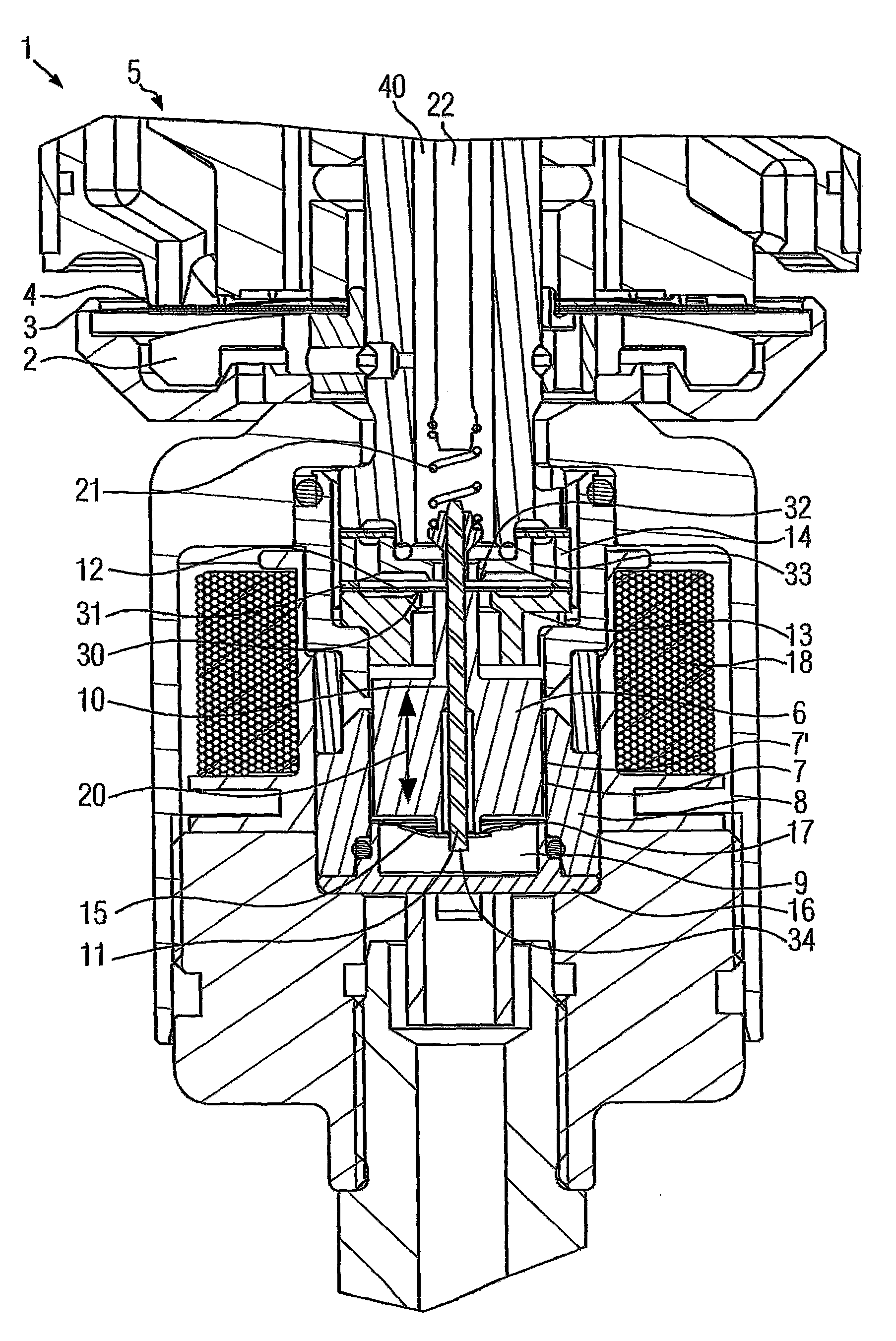
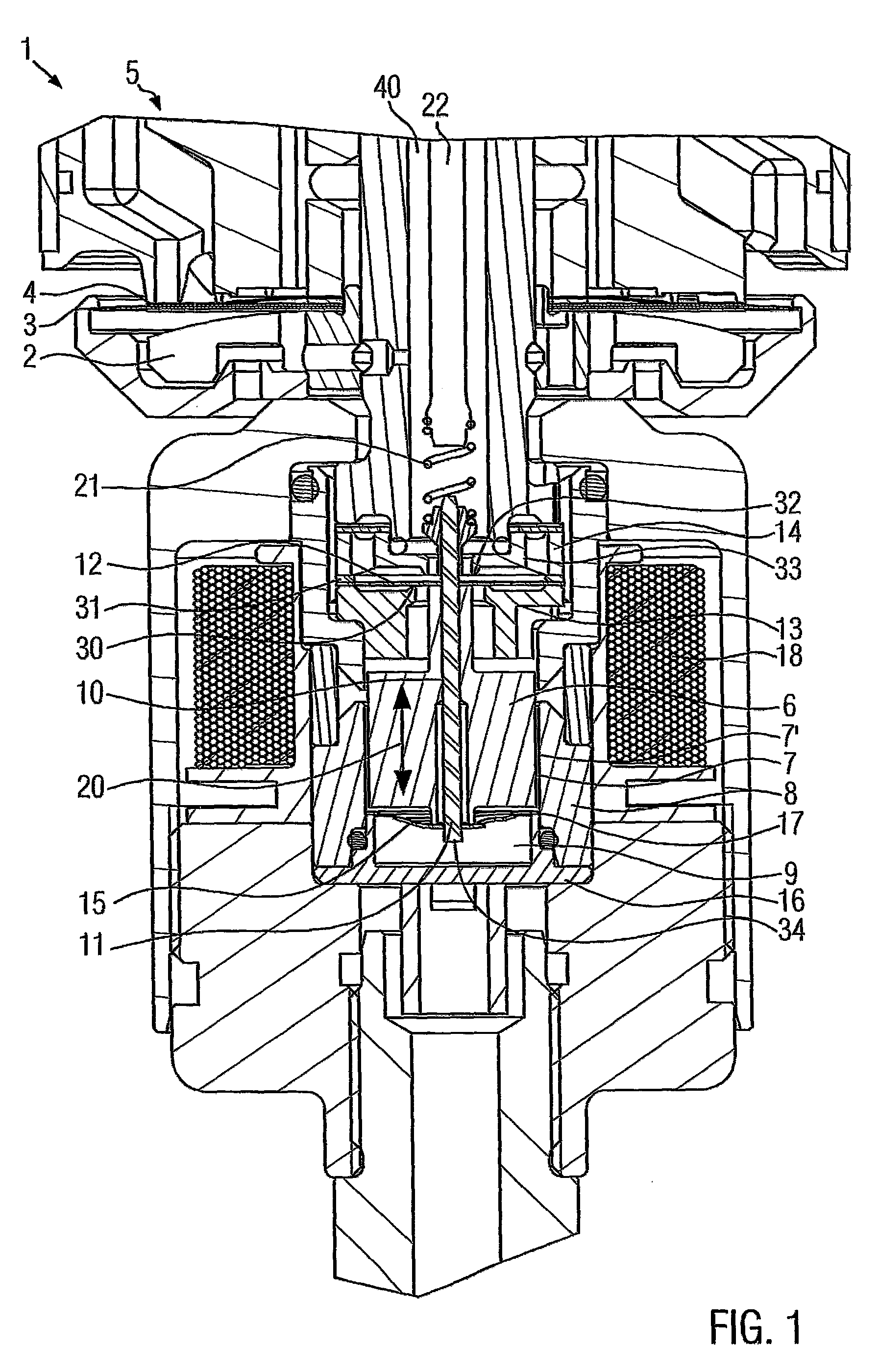
[0025]There is disclosed hereby damping valve arrangement for controlling a pilot pressure that exerts influence on a control chamber of a damping device of a vibration damper by means of a control fluid, with an armature that is displaceable by means of an electrically exercisable coil and provided in a housing. The armature comprises a guide pin on which a first spring washer is provided and braces the guide pin. The damping valve arrangement may be fitted as a pressure control unit in a telescopic suspension fork strut of a motorcycle, for example, or in a shock absorber for some other type of motor vehicle.

[0026]The following disclosure also relates to a method for controlling a pilot pressure in a control chamber of a damping device of a vibration damper by means of a magnetically actuated armature of a valve arrangement, which armature changes the area of a flow-through opening in the valve arrangement, through which a control fluid flows.

[0027]German Patent Application No. DE...


PUM


Abstract

A damping valve arrangement is provided for controlling a pilot pressure that exerts influence on a control chamber of a damping device of a vibration damper through a control fluid, with an armature that is displaceable by the activity of an electrically energizable coil and provided in a housing, which armature includes a guide pin on which a first spring washer is provided and braces the guide pin. The first spring washer is designed for changing the area of a flow-through opening of the damping valve arrangement through which a control fluid is able to flow.

Description

CROSS-REFERENCE TO RELATED APPLICATIONS[0001]This application claims the filing benefit of and priority to German Patent Application No. DE 10 2012 112 729.8 filed on 20 Dec. 2012, the entirety of which is incorporated herein by reference.BACKGROUND OF THE INVENTION[0002]1. Field of the Invention[0003]The present invention relates to damping valves, specifically a damping valve arrangement for controlling a pilot pressure that exerts influence on a control chamber of a damping device of a vibration damper by means of a control fluid, with an armature that is displaceable by means of an electrically exercisable coil and provided in a housing. The armature comprises a guide pin on which a first spring washer is provided and braces the guide pin.[0004]The invention further relates to a method for controlling a pilot pressure in a control chamber of a damping device of a vibration damper by means of a magnetically actuated armature of a valve arrangement, which armature changes the area...

Claims


Application Information

Patent Timeline
Patent Type & Authority Patents(United States)
IPC IPC(8): F16F9/34F15B11/044F16F9/46F16F9/348
CPCF15B11/0445F16F9/465F16F9/3484Y10T137/0396F16F1/027
Inventor WIMMER, JOHANNES
Owner KTM COMPONENTS GMBH
Why Eureka
Try Eureka