
Display for a pinball game

a display and pinball technology, applied in the field of pinball games, can solve the problems of not being as bright or uniform as those viewed directly on a conventional video display, and the display is located away from the player's view of the playfield

Inactive Publication Date: 2017-07-18
POPADIUK JOHN A
View PDF18 Cites 0 Cited by
  • Summary
  • Abstract
  • Description
  • Claims
  • Application Information

AI Technical Summary

Benefits of technology

[0011]In one embodiment, the display can be located at a rear portion of the playfield, and can be substantially vertical. Such position and orientation can facilitate viewing of images on the display, including player scores and other gameplay-related information, by a player without directing the player's field of view away from the playfield itself. The vertical display orientation can also provide illumination to a portion of the playfield, and can be arranged such that little or none of the playfield is obscured by the display, allowing more playfield area to be used by playfield features. In further embodiments, the display can be provided in other locations on or near the playfield.

Problems solved by technology

A major drawback of mounting the display in the backbox is that the display is located away from the player's view of the playfield.
This system provides some apparent interaction between motion of the pinball and some reflected graphical display elements, but it requires a specialized cabinet with a monitor mounted overhead and special glass over the playfield that has certain reflective qualities, and the graphical images are not as bright or uniform as those viewed directly on a conventional video display.

Method used


Image

  • Display for a pinball game
  • Display for a pinball game
  • Display for a pinball game

Examples


Embodiment Construction

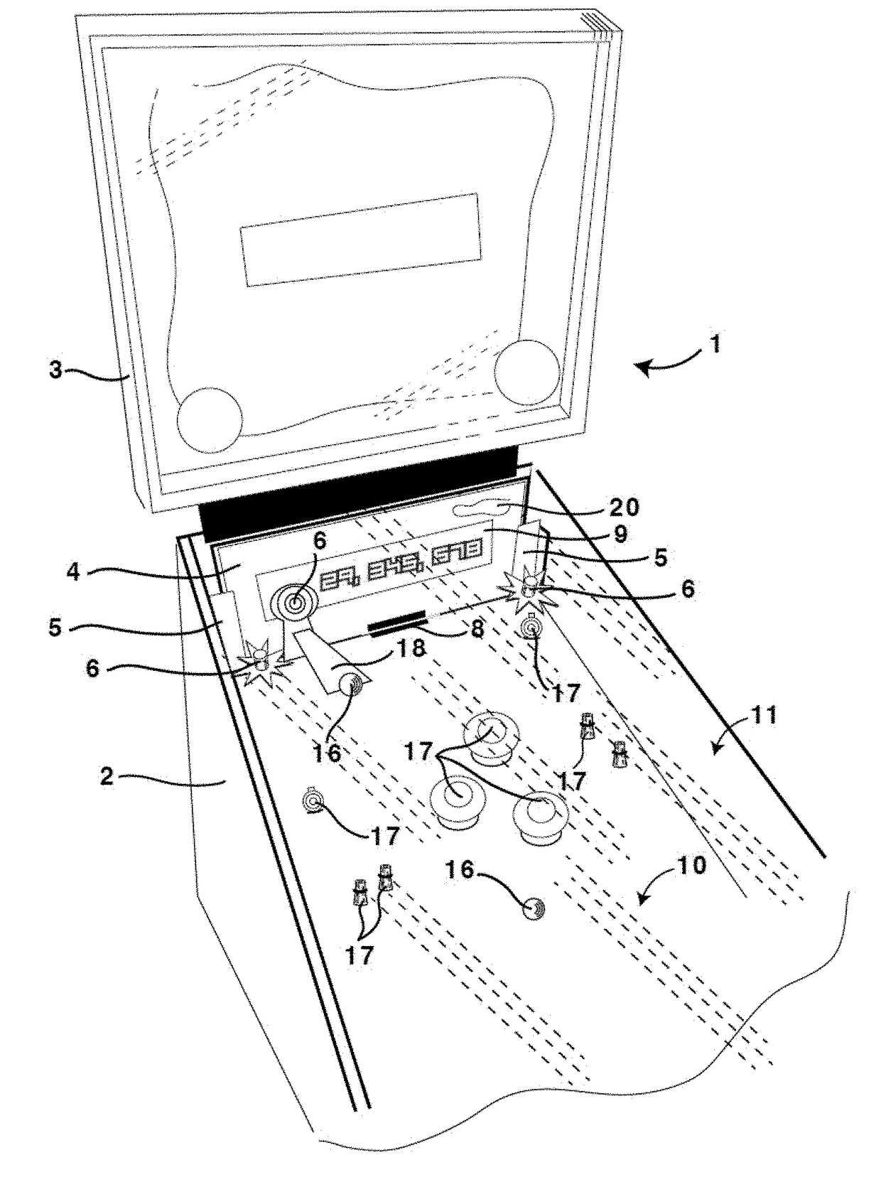
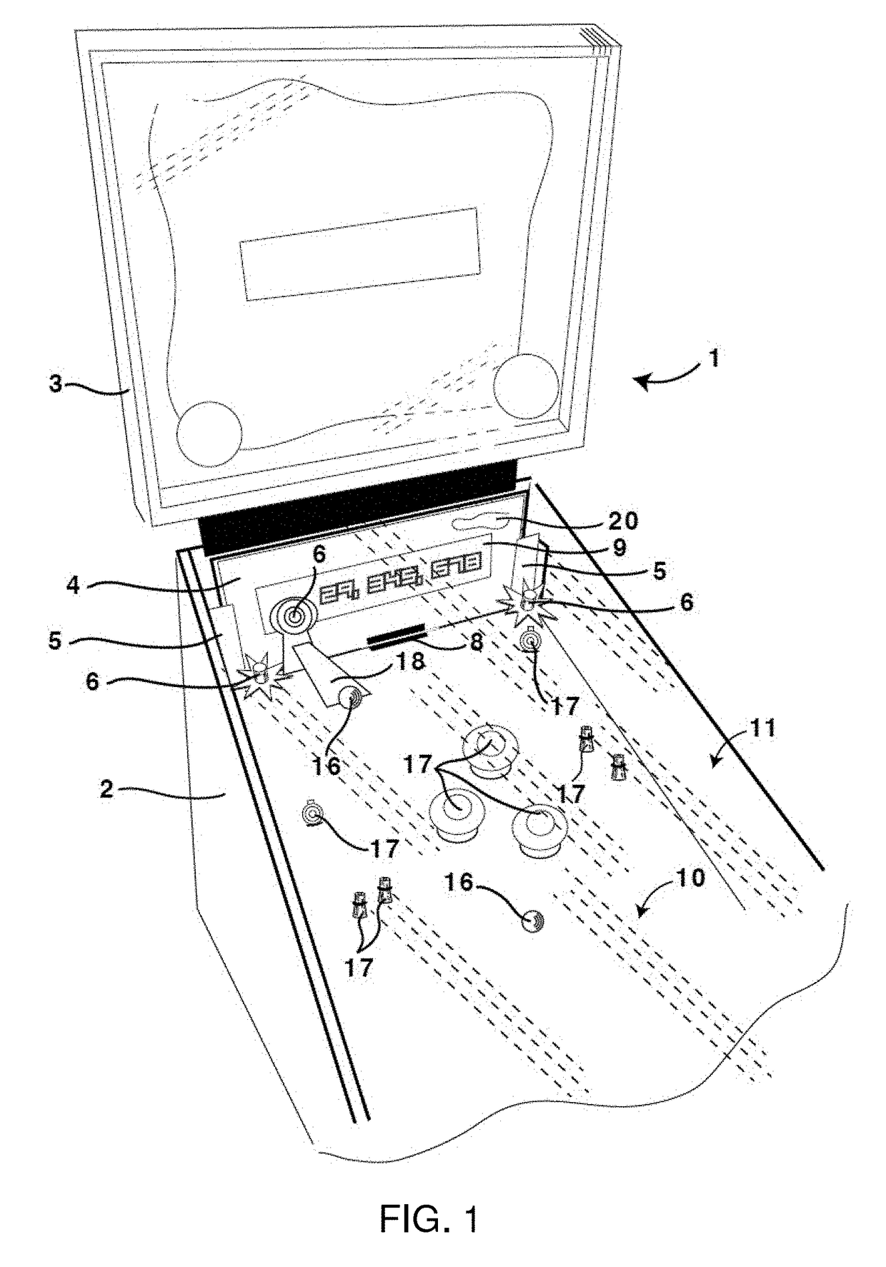
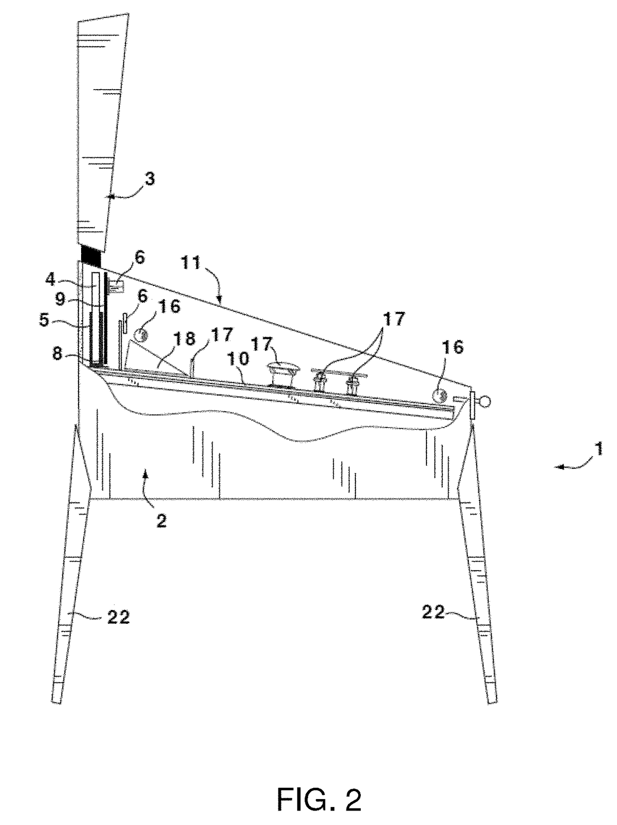
[0028]FIG. 1 shows an illustration of a rearward portion of a pinball machine 1 in accordance with exemplary embodiments of the present disclosure. The pinball machine 1 includes a playfield surface 10 provided in a game cabinet 2, and a clear glass panel 11 mounted along an upper surface of the cabinet 2, over the playfield 10. A backbox 3 is mounted over a rearward portion of the cabinet 2. Game elements 17, such as pop bumpers, lane guides, saucers, spinners, standup targets, and the like, as well as one or more ramps 18, can be provided on the playfield, and one or more pinballs 16 can be located on the playfield 10.

[0029]The pinball machine 1 can include a video display 4 provided on or proximal to the playfield 10. For example, the display 4 can be provided in a substantially vertical orientation at the rearward portion of the playfield 10 as shown in FIG. 1. Such orientation can provide good visibility of the display 4 by a player in front of the pinball machine 1, while not ...


PUM


Abstract

A pinball machine or other entertainment device is provided that includes a video display and one or more sensors proximal to the display that can detect proximity of or contact with an object such as a pinball. Graphical images and / or animations can then be shown on the display, such that the images appear to directly interact with, or result from apparent contact with, the pinball or other object to provide an enhanced gameplay experience for the player.

Description

CROSS-REFERENCE TO RELATED APPLICATION[0001]This application claims priority to U.S. Provisional Application Ser. No. 61 / 568,817, filed on Dec. 9, 2011, which is incorporated herein by reference in its entirety.FIELD OF THE DISCLOSURE[0002]The present disclosure relates generally to pinball games, and more specifically, to an interactive pinball game display located in close proximity to a rear portion of a pinball playfield, such that the display can be easily viewed by a player during game play and further providing visual features that can interact with physical objects in the pinball game.BACKGROUND INFORMATION[0003]A pinball machine typically includes an inclined playfield housed within a game cabinet, where the playfield is configured to support one or more rolling balls (pinballs) and a plurality of mechanical features that can interact with the ball(s) to score points and / or activate certain features of the game. A vertically-oriented backbox typically extends upward from a ...

Claims


Application Information

Patent Timeline
Patent Type & Authority Patents(United States)
IPC IPC(8): A63F7/02A63F7/30
CPCA63F7/027A63F7/02A63F7/307
Inventor POPADIUK, JOHN A.
Owner POPADIUK JOHN A
Learn More