Method for synchronizing display elements in a control system for automated control of a technical installation

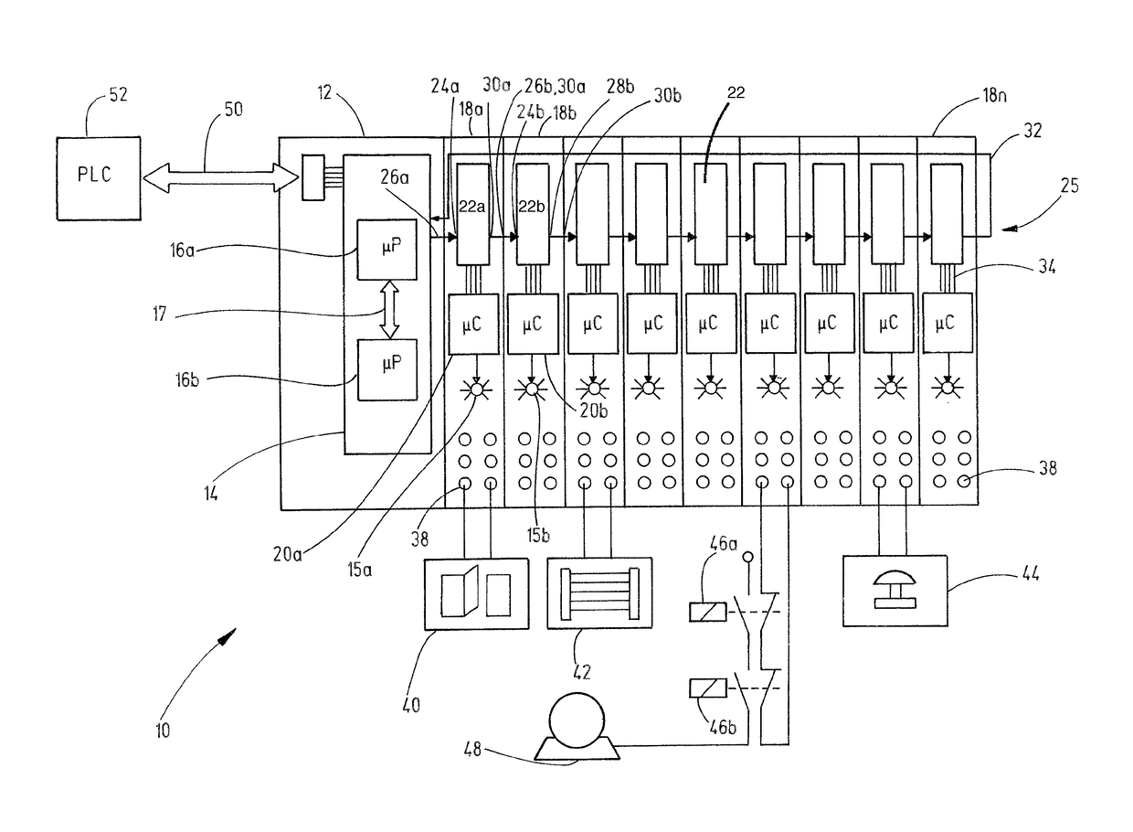
a technology of display elements and control systems, applied in computer control, electric digital data processing, instruments, etc., can solve problems such as irritating users, modules that do not work, and people's injuries, and achieve the effect of increasing user friendliness and/or safety, and simple and/or inexpensive manner

Inactive Publication Date: 2017-07-25
PILZ (COMPANY)
View PDF22 Cites 0 Cited by
  • Summary
  • Abstract
  • Description
  • Claims
  • Application Information

AI Technical Summary

Benefits of technology

The method ensures that display elements are toggled in sync, improving user friendliness and simplifying diagnosis by maintaining synchronous twinkling or flashing, reducing bus load, and leveraging existing structures within the control system.

Problems solved by technology

In particular, it involves the monitoring and control of installations operating in an automated fashion that have a risk of injury to people arising from their operation.
One disadvantage is that said modules do not twinkle or flash in sync with one another.
This can be irritating to the user, particularly because the modules are arranged close to one another or directly next to one another.
In addition, out-of-sync twinkling or flashing can make simple “first-level” diagnosis difficult for the user.
Such methods for synchronizing the time or time control methods are very involved and may produce a high bus load, however.

Method used


Image

  • Method for synchronizing display elements in a control system for automated control of a technical installation
  • Method for synchronizing display elements in a control system for automated control of a technical installation
  • Method for synchronizing display elements in a control system for automated control of a technical installation

Examples


example 1

[0121]There follows a first example with a very short bus message time interval Tbus. The following parameter values are assumed:

[0122]W=65 536

[0123]TBus=63 μs

[0124]V*twinkle=½

[0125]V*flash=⅕

[0126]T*ea=1 000 000 μs=1 s

[0127]A processor with floating point computation then performs the following calculations:

TW=W·Tbus=65 536·63 μs=4 128 768 μs

F=round(TW / T*ea)=round(4 128 768 μs / 1 000 000 μs)=round(4 128 768)=4

Utwinkle=round(W·V*twinkle)=round(65 536·½)=32 768

Uflash=round(W·V*flash)=round(65 536·⅕)=13 107

[0128]By contrast, a processor without floating point computation performs the following calculations:

TW=W·Tbus=65 536·63 μs=4 128 768 μs

F=(TW+Tea / 2) / T*ea=(4 128 768 μs+1 000 000 μs / 2) / 1 000 000 μs=(4 128 768 μs+500 000 μs) / 1 000 000 μs=4 628 768 μs / 1 000 000 μs=4

Utwinkle=W·V*twinkle=65 536 / 2=32 768

Uflash=W·V*flash=65 536 / 5=13 107

[0129]The following pseudo code is obtained for the first example:

[0130]

 If (LED == target_twinkle) { If ((Z% 16 384)   {  LED = on  } else  {  LED = off  }}...

example 2

[0133]There follows a second example with a very long bus message time interval TBus. The following parameter values are assumed:

[0134]W=65 536

[0135]TBus=10 000 μs

[0136]V*twinkle=½

[0137]V*flash=⅕

[0138]T*ea=1 000 000 μs=1 s

[0139]A processor without floating point computation performs the following calculations:

TW=W·Tbus=65 536·10 000 μs=655 360 000 μs

F=(TW+T*ea / 2) / T*ea=(655 360 000 μs+500 000 μs) / 1 000 000 μs=655

Utwinkle=W·V*twinkle=65 536 / 2=32 768

Uflash=W·V*flash=65 536 / 5=13 107

[0140]The following pseudo code is obtained:

[0141]

 If (LED == target_twinkle) { If ((Z% 100)   {  LED = on  } else  {  LED = off }}If (LED == target_flash) { If ((Z% 100)   {  LED = on  } else  {  LED = off  }}

[0142]For this second example, the following is therefore obtained for the percentage discrepancy:

Δ%=[((655 360 000 μs / 655)−1 000 000 μs)*100] / 1 000 000 μs=0.055%

[0143]The discrepancy in the actual twinkling / flashing from the desired twinkling / flashing is small in this case, since the division remainder...

example 3

[0145]The third example, below, shows the greatest possible discrepancy. By way of example, this is the case if a remainder of ½·T*ea were to be obtained for the division or the quotient of the value range period TW by the desired on / off period T*ea. In the present specific example, the greatest possible discrepancy would be obtained when the value range period TW is in the range around 4.5 s for a desired on / off period of 1 s. This will be the case, during the constant value range, with a bus message time interval Tbus of approximately 69 μs. Therefore, the following parameter values are assumed:

[0146]W=65 536

[0147]TBus=69 μs

[0148]V*twinkle=½

[0149]V*flash=⅕

[0150]T*ea=1 000 000 μs=1 s

[0151]A processor without floating point computation then performs the following calculations:

TW=W·Tbus=65 536·69 μs=4 521 984 μs

F=(TW+T*ea / 2) / T*ea=(4 521 984 μs+500 000 μs) / 1 000 000 μs=5

Utwinkle=W·V*twinkle=65 536 / 2=32 768

Uflash=W·V*flash=65 536 / 5=13 107

[0152]The following pseudo code is obtained:

[015...


PUM


Abstract

A method for synchronizing display elements of a plurality of subscribers of a distributed, bus-based control system is proposed. The subscribers comprise a message transmitter and a plurality of message receivers. The message receivers each comprise a respective display element, which can be toggled between a switched-on state and a switched-off state, and a control unit for producing a control signal for toggling the display element from one state to the other. The message transmitter sends a respective current bus message via the bus in defined recurring bus message time intervals. The respective bus message comprises a bus message counter that has a respective value from a defined value range. The counter value is changed in a predefined manner each time when a current bus message is sent. The message receivers receive the respective bus messages via the bus. The control units each evaluate the respective bus message counter in the same manner and take this as a basis for producing the control signal, so that the display elements are toggled between the switched-on state and the switched-off state in sync with one another and with a defined on / off period.

Description

CROSS-REFERENCES TO RELATED APPLICATIONS[0001]This application is a continuation of international patent application PCT / EP2013 / 065096 filed on Jul. 17, 2013 designating the U.S., which international patent application has been published in German language and claims priority from German patent application DE10 2012 106 601.9 filed on Jul. 20, 2012. The entire contents of these priority applications are incorporated herein by reference.BACKGROUND OF THE INVENTION[0002]The present invention relates to a method for synchronizing display elements which are arranged in and distributed over a plurality of subscribers of a control system for the automated control of a technical installation.[0003]By way of example, a pertinent control system is a programmable controller, as marketed under the trademark PSS® by the assignee and described in “PSSuniversal, Programmable Control Systems PSS®, System Description, No. 21256-EN-04”. This control system is used for the automated control of a tech...

Claims


Application Information

Patent Timeline
Patent Type & AuthorityPatents(United States)
IPC IPC(8): G05B19/042G05B15/02G06F13/42
CPCG06F13/4221G05B15/02G05B19/0428G05B2219/23172
InventorGODAU, THORSTENADAMS, CHRISTIANSPERRER, REINHARDSEIZINGER, DIETMAR
OwnerPILZ (COMPANY)