Method for operating an internal combustion engine

a technology of internal combustion engine and valve lift, which is applied in the direction of machines/engines, electric control, instruments, etc., to achieve the effect of diagnosing an erroneous valve li

Inactive Publication Date: 2006-06-27
ROBERT BOSCH GMBH
View PDF3 Cites 13 Cited by
  • Summary
  • Abstract
  • Description
  • Claims
  • Application Information

AI Technical Summary

Benefits of technology

[0002]The method according to the present invention for operating an internal combustion engine has the advantage over the related art that a value for a specific cylinder, which is representative of the air / fuel ratio in that cylinder, is determined in an exhaust system branch of the internal combustion engine, and at least one such value is compared with a predefined value, and an erroneous lift of the intake valve is diagnosed as a function of the deviation of this at least one value from the predefined value. This makes it possible to diagnose an erroneous valve lift of each individual intake valve, and to determine which cylinder has the defective intake valve. This does not require sensors in the particular intake valve.
[0003]It is particularly advantageous if the at least one value is determined using a lambda sensor in the exhaust system branch. In this way, it is possible to use an existing lambda sensor and to diagnose the valve lift without additional sensors in a consequently simple and inexpensive manner.
[0004]Another advantage results if the at least one value is representative of the air / fuel ratio in the cylinder associated with the intake valve to be diagnosed. This makes it possible to directly diagnose the valve lift of the intake valve of the associated cylinder by comparing the at least one value with the predefined value. This is accomplished in a particularly simple and inexpensive manner.

Problems solved by technology

In this way an erroneous valve lift of an intake valve may be diagnosed at least indirectly in a very simple manner, but, depending on the number of cylinders, does not allow determination of which cylinder has the defective intake valve, and usually requires analysis of a plurality of such values for this purpose.

Method used


Image

  • Method for operating an internal combustion engine
  • Method for operating an internal combustion engine
  • Method for operating an internal combustion engine

Examples


Embodiment Construction

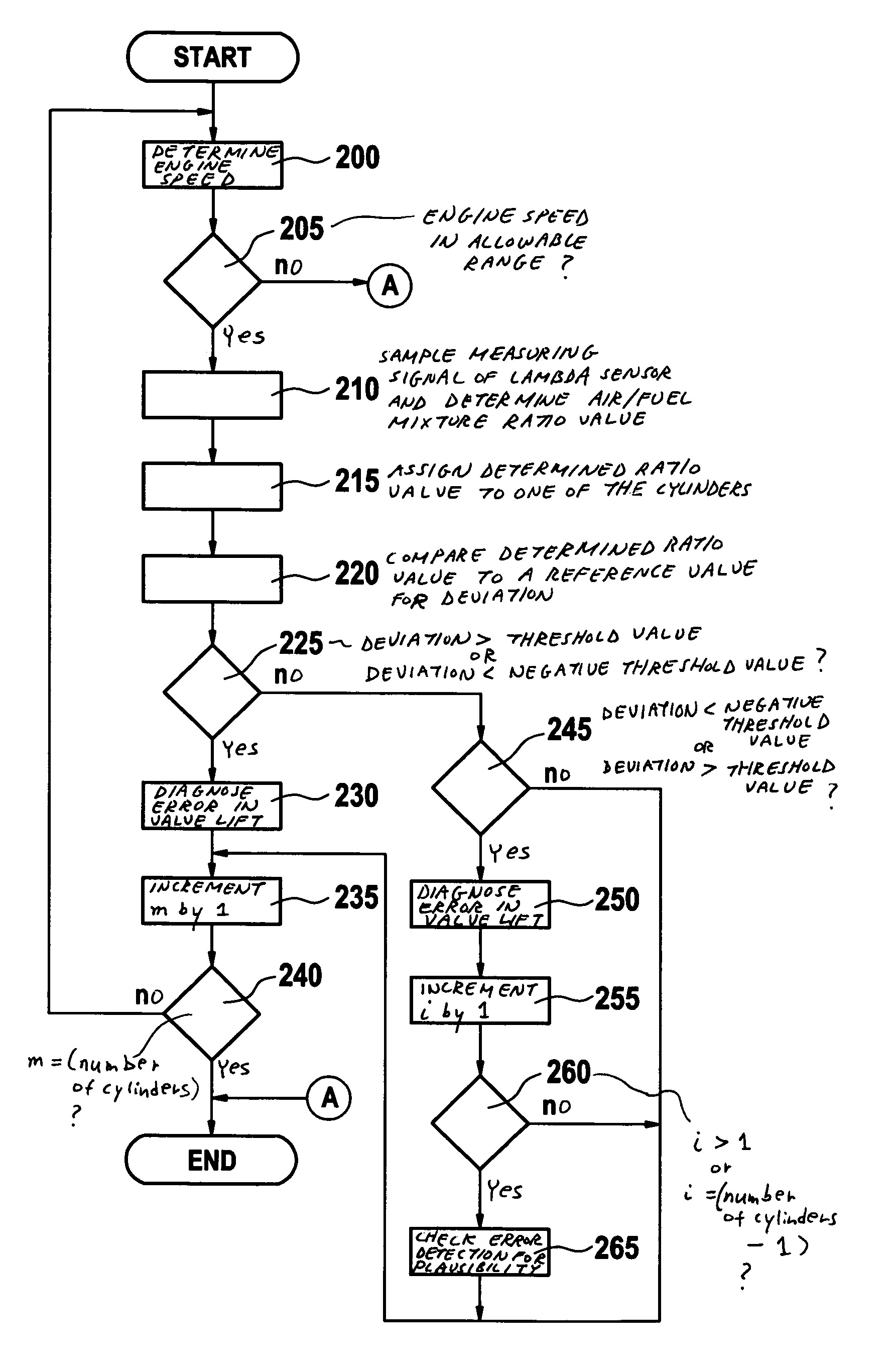
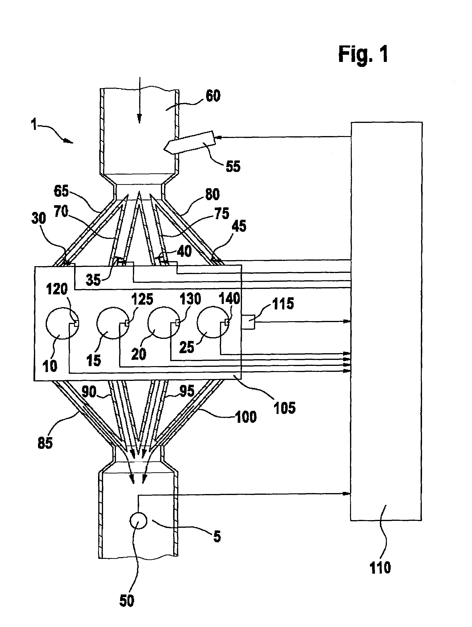
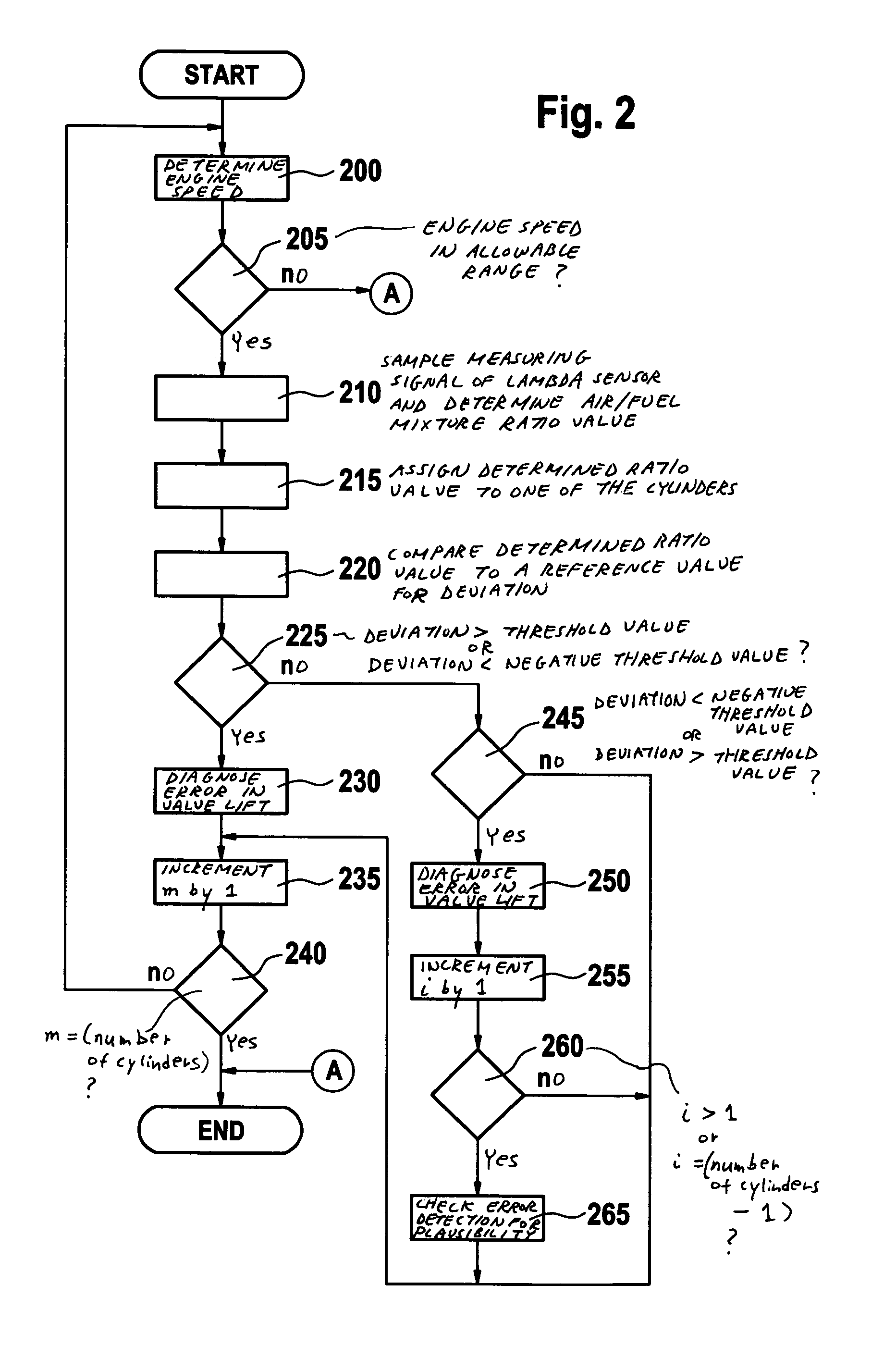
[0013]In FIG. 1, reference numeral 1 designates an internal combustion engine, of a motor vehicle in particular. Internal combustion engine 1 includes a combustion engine 105, which may be designed as a gasoline engine or a diesel engine. In the following it will be assumed as an example that combustion engine 105 is designed as a gasoline engine. Also as an example, combustion engine 105 has four cylinders 10, 15, 20, 25. Combustion engine 105 receives fresh air via air supply 60. Injector 55, through which fuel is injected into a section of air supply 60 designated as an intake pipe and not shown in detail in FIG. 1, is positioned in air supply 60. The fuel mass to be injected is set by a controller 110, for example, by controlling the injection time and an injection pressure of injector 55. The fuel mass to be injected is determined by controller 110 for setting a desired air / fuel mix ratio. As an alternative to the implementation of the injection as illustrated and described abo...


PUM


Abstract

A method for operating an internal combustion engine, in which an erroneous lift of an intake valve of a cylinder is directly determined. The lift of an intake valve of at least one cylinder of the internal combustion engine is diagnosed. A value for a specific cylinder which is representative of the air / fuel ratio in the respective cylinder is determined in an exhaust system branch of the internal combustion engine. At least one such value is compared to a predefined value. An erroneous lift of the intake valve is diagnosed as a function of the deviation of this at least one value from the predefined value.

Description

BACKGROUND INFORMATION[0001]Methods for operating an internal combustion engine are known in which the lift of an intake valve of an engine cylinder is diagnosed. This is accomplished using optical or electronic sensor systems in the corresponding intake valve itself and thus involves considerable hardware complexity. Diagnosing the valve lift of the intake valves via the uneven running of the engine is also known. However, this only works in a satisfactory manner during idling and at higher speeds. Finally, diagnosing the valve lift of the intake valve via partial vibrations in the camshaft is also known. However, in this case it is impossible to determine which cylinder has the defective intake valve.SUMMARY OF THE INVENTION[0002]The method according to the present invention for operating an internal combustion engine has the advantage over the related art that a value for a specific cylinder, which is representative of the air / fuel ratio in that cylinder, is determined in an exha...

Claims


Application Information

Patent Timeline
Patent Type & Authority Patents(United States)
IPC IPC(8): G01M15/10F01L13/00F01L3/24F02D13/02F02D41/04F02D41/14F02D41/22F02D43/00G01M15/00
CPCF01L3/24F02D13/0226F02D41/221F02D41/1454F01L1/46F01L13/0015F01L2800/12F01L2800/11F02D2250/16Y02T10/40Y02T10/18Y02T10/12
Inventor KELLER, TORSTENYILMAN, SINANKOEHLER, BORISSCHULER, CHRISTIAN
Owner ROBERT BOSCH GMBH
Why Eureka
Try Eureka