
Bulk bag

Active Publication Date: 2004-08-19
TELLAP
View PDF11 Cites 12 Cited by
  • Summary
  • Abstract
  • Description
  • Claims
  • Application Information

AI Technical Summary

Benefits of technology

[0010] It is an object of this invention to provide a bulk bag and tubular tine receiving elements that are simple to produce and wherein the maintenance of the members within a flexible sleeve or pocket is achieved in a simple and inexpensive manner and wherein at least some protection may be afforded to a bag at the entrance to a tubular element.

Problems solved by technology

It has long been realised that lifting a filled bulk bag from the top restricts the height to which bags can be stacked in a transport container because of the restriction imposed by the roof of the container.
These bases occupy volume with a corresponding decrease in available space for load and would also be rather costly to manufacture as they must be rather strong.
Timber is costly; very much out of fashion; and even not accepted in some destinations, unless properly treated.
Extrusions would have to be rather robust to withstand the substantial transverse forces imposed on them and extrusion of a tubular element does not allow for reinforcing ribs to be formed transverse to the length of the element.
Elastic entrances to the sleeves effectively narrow the entrances to the receiving members and make it more difficult for a forklift truck driver to align the free ends of the tines with the openings.
This, accordingly, increases the already present possibility that the side of the bag immediately adjacent the entrance to such a tubular element may be damaged by the tines of the forklift truck during attempts to align the tines with the interior of the tubular element.
Also, the alternative constructions, namely a pair of cooperating clipping extrusions, are expensive; relatively complicated; and also suffer from the disadvantage that reinforcing ribs transverse to the length of the extrusions cannot be easily formed.
The alternative of injection moulding such components is also extremely expensive with die-costs for such large items generally being substantial.

Method used


Image

  • Bulk bag
  • Bulk bag
  • Bulk bag

Examples


Embodiment Construction

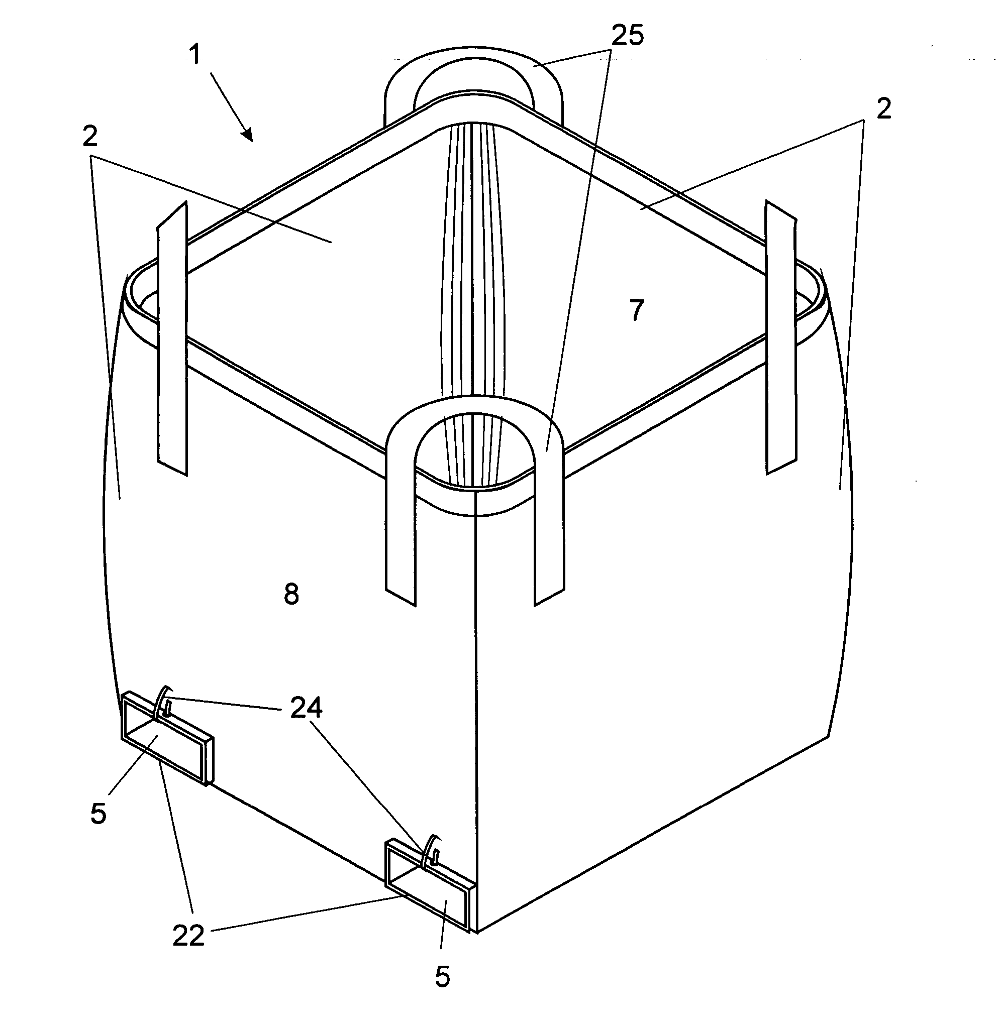
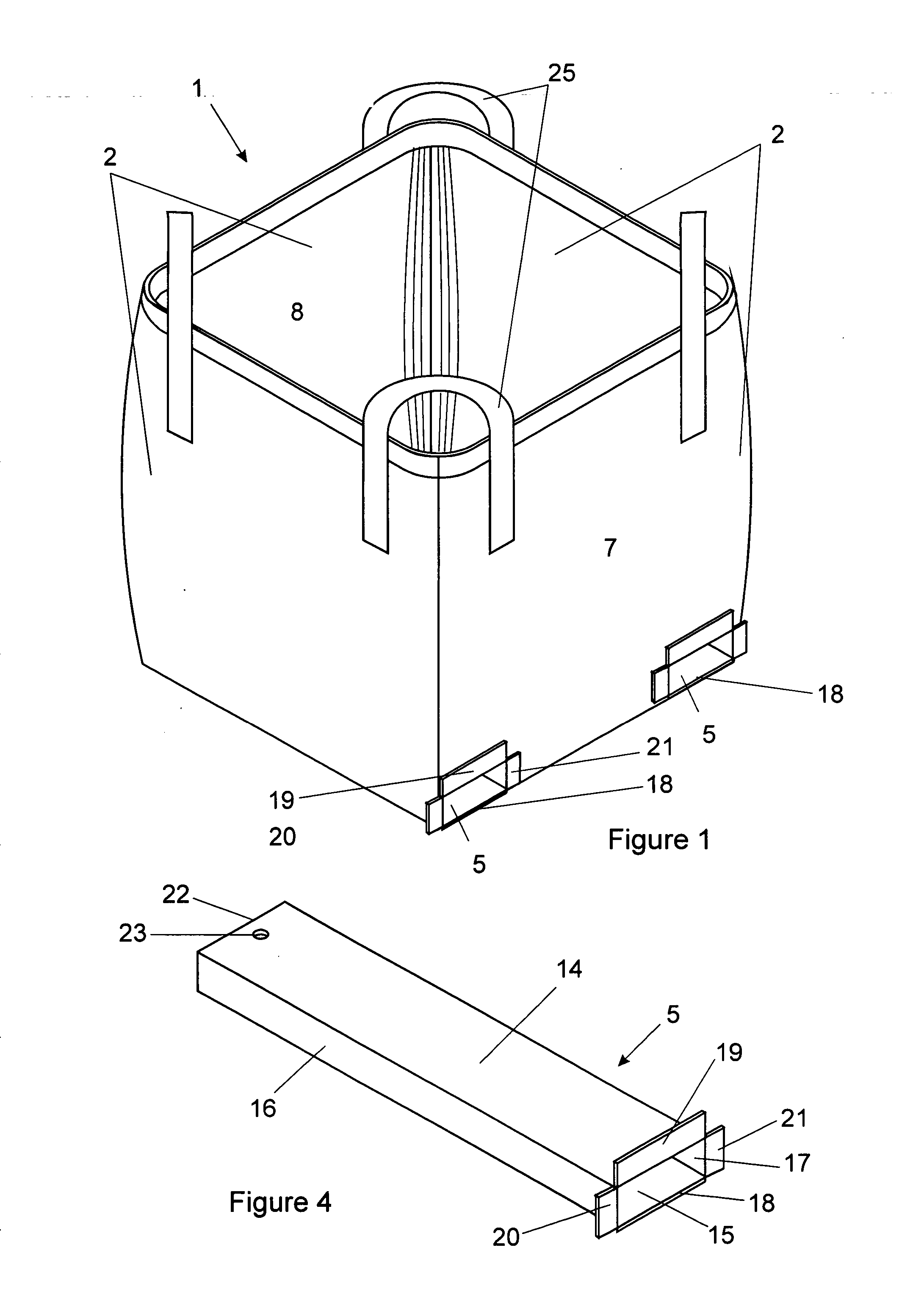
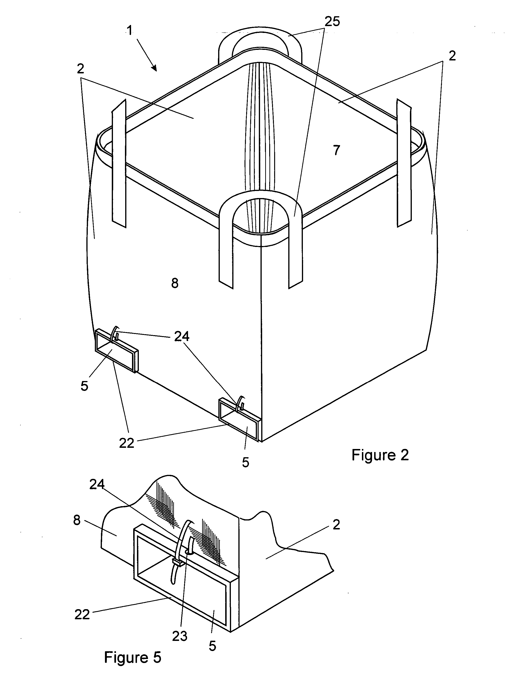
[0027] In the illustrated embodiment of the invention, a bulk bag, generally indicated by numeral (1), is made by substantially conventional manufacturing techniques of cutting and stitching and / or thermally bonding a suitable woven fabric material, typically a woven polypropylene or other suitable material. The bulk bag has sidewalls (2) and a bottom wall (3), the bottom wall being adapted to rest on the ground or floor that is indicated by numeral (4) in FIG. 3. This arrangement means that the majority of the substantial weight of a filled bag is exerted directly on the floor and only a small portion is exerted on the tubular elements that described below.

[0028] In order to accommodate generally squat rectangular cross-sectioned tubular elements (5) that, in use receive the tines of a forklift truck, there are formed two sleeves (6) that extend generally parallel to each other, one in each corner of the bag where the relevant side wall joins the bottom wall so as to extend from wh...


PUM


Abstract

A bulk bag having side walls; and a bottom wallis provided wherein a pair of laterally spaced generally flexible sleeves are associated with the bottom wall with each sleeve operatively receiving a generally rigid tubular element adapted to receive a tine of a forklift truck, in use. Each tubular element preferably has, at one end thereof, outwardly directed flange formations for preventing movement of the said end into the sleeve, in use, and means at the other end for inhibiting movement of said other end into the sleeve, in use. The tubular element is preferably made to a generally rectangular cross-sectional configuration from a flat sheet of material bent along the corners to define said tubular element. The flat sheet of material is preferably an extruded sheet of plastics material having a series of integral spaced parallel webs or ribs of material strengthening the sheet in which case bends defining the corners of said generally rectangular cross-sectional configuration extend at substantially right angles to the length of said webs or ribs.

Description

[0001] This invention relates to bulk bags widely used for transporting bulk commodities from one place to another and wherein the filled bulk bags are often packed into shipping containers or closed road or rail transport vehicles (herein collectively referred to generally as a transport containers).BACKGROUND TO THE INVENTION[0002] Bulk bags are becoming increasingly popular for the purpose of transporting commodities that range from mined ores and minerals, in either granular or lumpy form, to agricultural products, chemicals, small hardware components and small packages of many different small products.[0003] For the purpose of stacking filled bulk bags into transport containers it is generally advantageous to move the filled bags using a forklift truck. It has long been realised that lifting a filled bulk bag from the top restricts the height to which bags can be stacked in a transport container because of the restriction imposed by the roof of the container.[0004] As a result,...

Claims


Application Information

Patent Timeline
IPC IPC(8): B65D88/16
CPCB65D88/1687B65D88/1668B65D31/16B65D33/00
Inventor VON MERVELDT, ALF BERND MICHAEL
Owner TELLAP
Learn More