
Composite particle, method of producing same, resin composition containing the particle, reflector formed from the composition, and light-emitting semiconductor device using the reflector

Inactive Publication Date: 2015-03-05
SHIN ETSU CHEM IND CO LTD
View PDF2 Cites 0 Cited by
  • Summary
  • Abstract
  • Description
  • Claims
  • Application Information

AI Technical Summary

Benefits of technology

The patent describes a method for producing a composite particle that consists of silica and an inorganic compound particle, such as a metal oxide, integrated together. The composite particle can be made by mixing silica and the inorganic compound particles together and sintering them at a high temperature. The resulting composite particle has improved stability and can be used in various applications. The patent also provides methods for producing spherical composite particles and a specific range of silica and inorganic compound content for achieving good stability.

Problems solved by technology

However, reflectors formed from a thermoplastic resin or an epoxy resin or the like have a problem in that, when a high-brightness LED or the like is installed, the resin degrades and yellows due to the effects of temperature and light (Patent Documents 1 and 2).
Further, another problem arises because a large amount of a fine powder of titanium oxide or the like must be used to ensure a white color, and as a result, the flowability of the resin deteriorates, and when the reflector is molded by transfer or injection molding or the like, molding defects such as incomplete filling and voids tend to occur more frequently (Patent Document 3).
However, if silica is used as a filler material, then a problem arises in that some of the emitted light escapes due to similar refractive index of silica to that of the silicone resin (Patent Document 4).

Method used


Image

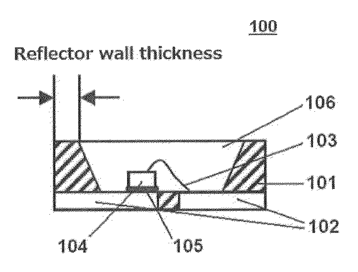
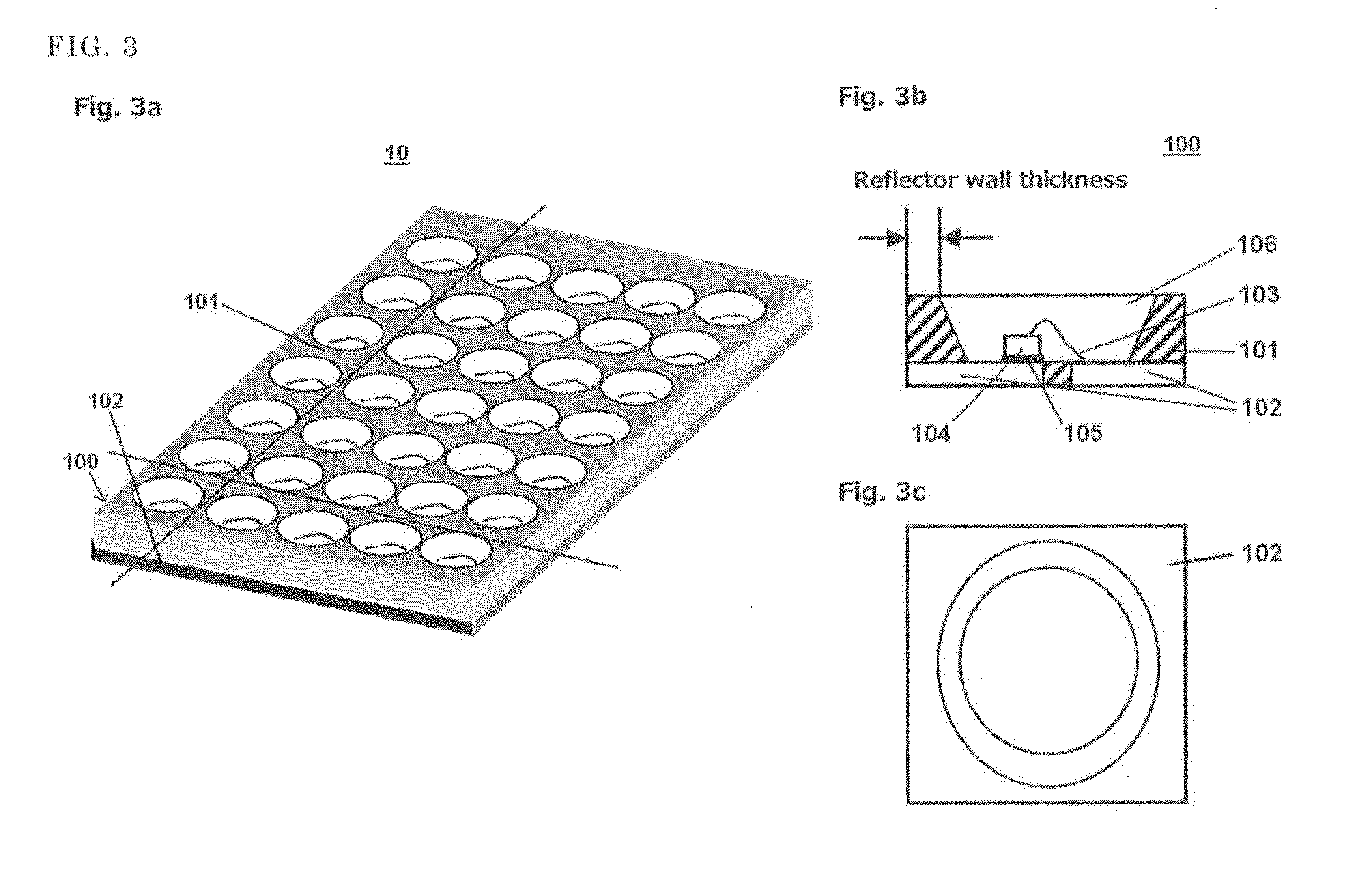
  • Composite particle, method of producing same, resin composition containing the particle, reflector formed from the composition, and light-emitting semiconductor device using the reflector
  • Composite particle, method of producing same, resin composition containing the particle, reflector formed from the composition, and light-emitting semiconductor device using the reflector
  • Composite particle, method of producing same, resin composition containing the particle, reflector formed from the composition, and light-emitting semiconductor device using the reflector

Examples


example 1

[0051]As shown in Table 1, fumed silica (SiO2) (Aerosil 380, manufactured by Nippon Aerosil Co., Ltd.), titanium dioxide (TiO2) (CR-60, manufactured by Ishihara Sangyo Kaisha, Ltd.), fumed alumina (Al2O3) (SpectrAl 100 manufactured by Cabot Corporation) and water were mixed together using a mixing device until a uniform mixture was obtained, thus producing a series of clay-like mixtures. Each of these mixtures was placed in a muffle furnace at 400° C., 600° C. or 800° C. and heat-treated for 5 hours, and was then cooled to room temperature to obtain a sintered product.

TABLE 1Rawmaterial(units:partsbyExampleExampleExampleExampleComponentmass)1A1B1C1D(1)Silica50703070(Aerosil380)(2)CR-60503020(TiO2)SpectrA1304010100(Al2O3)(3)Water10101010Evaluation results400° C.Partially insufficient sintered productsexist600° C.Vitrified800° C.

[0052]Following coarse crushing of the vitrified block produced by baking at 800° C. in each of Examples 1A to 1D, crushing was performed using a ball mill to...

example 2

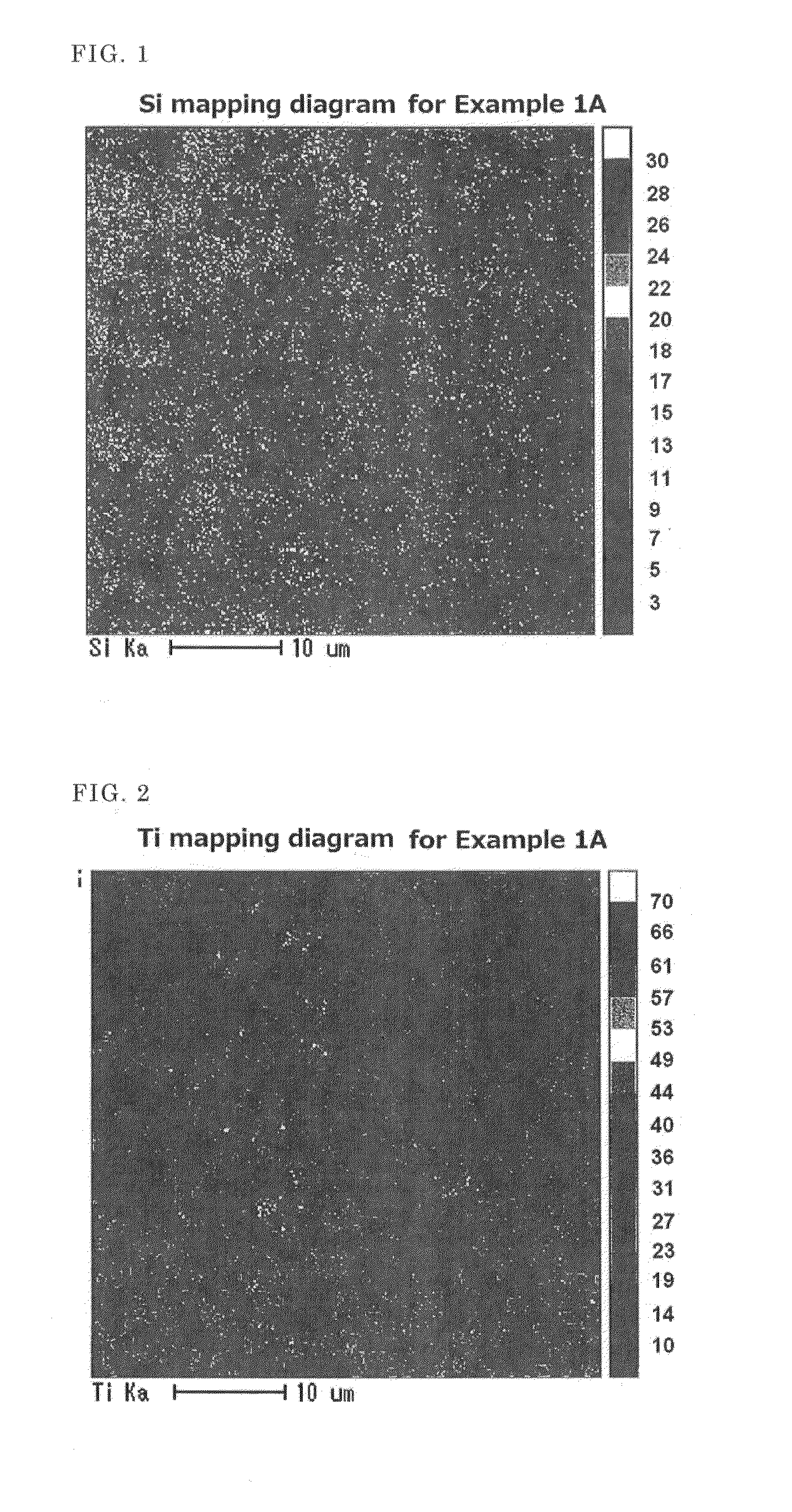
[0054]Each of the composite oxides obtained by baking at 400° C. in Examples 1A to 1D was crushed in a ball mill until a fine powder was obtained, and the crushed powder was then regulated using a sieve to obtain a particle size of 50 μm or less. Each of these powders was melted by sprinkling onto a flame at 2,000° C., and was then cooled, thereby producing a series of spherical composite oxides 2A to 2D. Each of these composite oxides was composed of particles having a spherical shape and a uniform composition distribution. The particle size distribution of each composite oxide is shown in Table 5. The numerical values in Table 5 indicate mass % values. In Example 1A, electron microprobe analyzer (EPMA) mapping diagrams of the silicon (Si) and the titanium (Ti) in the composite oxide obtained by baking at 400° C. are shown in FIG. 1 and FIG. 2, respectively.

TABLE 3ExampleExampleExampleExampleParticle size2A2B2C2Dgreater than 100μm101075 to 100μm1289450 to 75μm2012151530 to 50μm2535...

example 3

[0055]Raw materials (mixed fine powders) having a blend ratio shown in Table 4 were granulated in the presence of a small amount of water using a granulator. Each of the obtained granular powders was melted by sprinkling onto a flame at 2,000° C., thus producing a series of spherical composite oxide particles 3A to 3D. The particle size distribution of each of the obtained composite particles is shown in Table 5.

TABLE 4Rawmaterial(units:partsExampleExampleExampleExampleComponentby mass)3A3B3C3D(1)Silica50707070(Aerosil380)(2)Aeroxide502020TiO2 P25(TiO2)Aeroxide301010Alu C(Al2O3)(3)Water22210

TABLE 5ExampleExampleExampleExampleParticle size3A3B3C3Dgreater than 150μm1020100 to 150μm325275 to 100μm111418750 to 75μm3134362130 to 50μm2121213010 to 30μm171512251 to 10μm1111512less than 1μm5313

(A) Vinyl Group-Containing Organopolysiloxane


PUM

PropertyMeasurementUnit
Temperatureaaaaaaaaaa
Percent by massaaaaaaaaaa

Abstract

A composite particle comprises inorganic compound particles that are derived from inorganic particle and are uniformly dispersed and sintered in a matrix phase composed of silica, or comprises silica particles that are uniformly dispersed and sintered in a matrix phase composed of said inorganic compound particles. The composite particle is prepared by sintering a mixture of (1) finely powdered silica having a BET specific surface area of 50 m2 / g or greater, (2) an inorganic particle other than silica and (3) water at a temperature of 300° C. or higher to form a glass-like substance, and then crushing the glass-like substance. A spherical composite particle is prepared by melting and spheroidizing the mixture of (1)-(3) in a flame of 1,800° C. or higher. Also provided are a resin composition for a reflector for a light-emitting semiconductor device, a light-emitting semiconductor device that includes said reflector, and a light-emitting semiconductor device in which a light-emitting semiconductor element is encapsulated with said resin composition.

Description

BACKGROUND OF THE INVENTION[0001]1. Field of the Invention[0002]This invention relates to a reflector for a light-emitting semiconductor device that exhibits high light reflectance and is resistant to light transmission, a resin composition that is ideal for forming this reflector, and a composite particle that is added to the resin composition.[0003]2. Description of the Related Art[0004]Conventionally, reflectors for light-emitting semiconductor devices have typically been formed from compositions prepared by adding a white filler material such as titanium oxide, magnesium oxide or zinc oxide, and silica and the like to an epoxy resin or a silicone resin.[0005]However, reflectors formed from a thermoplastic resin or an epoxy resin or the like have a problem in that, when a high-brightness LED or the like is installed, the resin degrades and yellows due to the effects of temperature and light (Patent Documents 1 and 2). Further, another problem arises because a large amount of a fi...

Claims


Application Information

Patent Timeline
IPC IPC(8): H01L33/60H01L33/56C08K7/18B28B1/54C08K3/36C08K3/22
CPCH01L33/60C08K3/36C08K3/22C08K2003/2241B28B1/54H01L33/56C08K7/18C08K2201/006H01L24/97H01L2224/32245H01L2224/48091H01L2224/48247H01L2224/73265H01L2224/45144H01L2924/15747H01L2933/0058H01L2924/12042C08K3/34H01L2224/97Y10T428/2982H01L2924/00014H01L2924/00H01L2924/00012
Inventor SHIOBARA, TOSHIOTSUTSUMI, YOSHIHIRO
Owner SHIN ETSU CHEM IND CO LTD
Learn More