Chemical reactor with catalyst support system

Active Publication Date: 2019-10-31
HALDOR TOPSOE AS
View PDF2 Cites 0 Cited by
  • Summary
  • Abstract
  • Description
  • Claims
  • Application Information

AI Technical Summary

Benefits of technology

[0023]In a specific embodiment, the anti-blocking means have a triangular cross-sectional shape with rounded corners of the triangle. While simple to produce, the triangular cross-sectional shape ensures constructional strength and the rounded corners minimizes the risk of fragmenting and cracking of the anti-blocking means as well as the risk of damage to the catalyst or other reactor parts which contact the anti-blocking means.
[0024]The mentioned other reactor parts may in an embodiment comprise inert elements or shaped catalyst particles arranged around and possibly also on top of the catalyst support system as a layer between the other catalyst particles and the catalyst support system, which are specially geometrically shaped to contact and support on the anti-blocking means w

Problems solved by technology

Also the pressure loss of the fluid through the catalyst support system is critical, a high pressure loss increases the demand on blowers/pumps and in the end increases the cost of running the chemical reactor.
It is important that the flow channels are not blocked by the catalyst or other parts in the reactor, since this may lead to an increase of the pressure loss for the process fluid passing through

Method used


Image

  • Chemical reactor with catalyst support system
  • Chemical reactor with catalyst support system
  • Chemical reactor with catalyst support system

Examples


Embodiment Construction

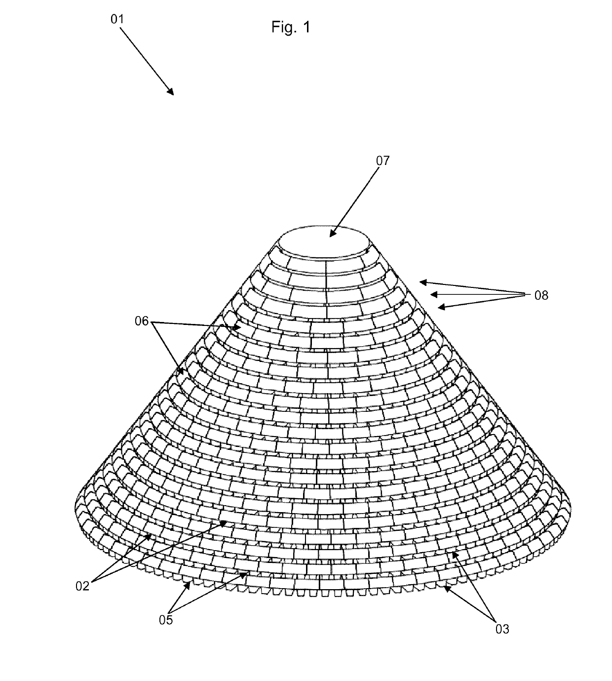
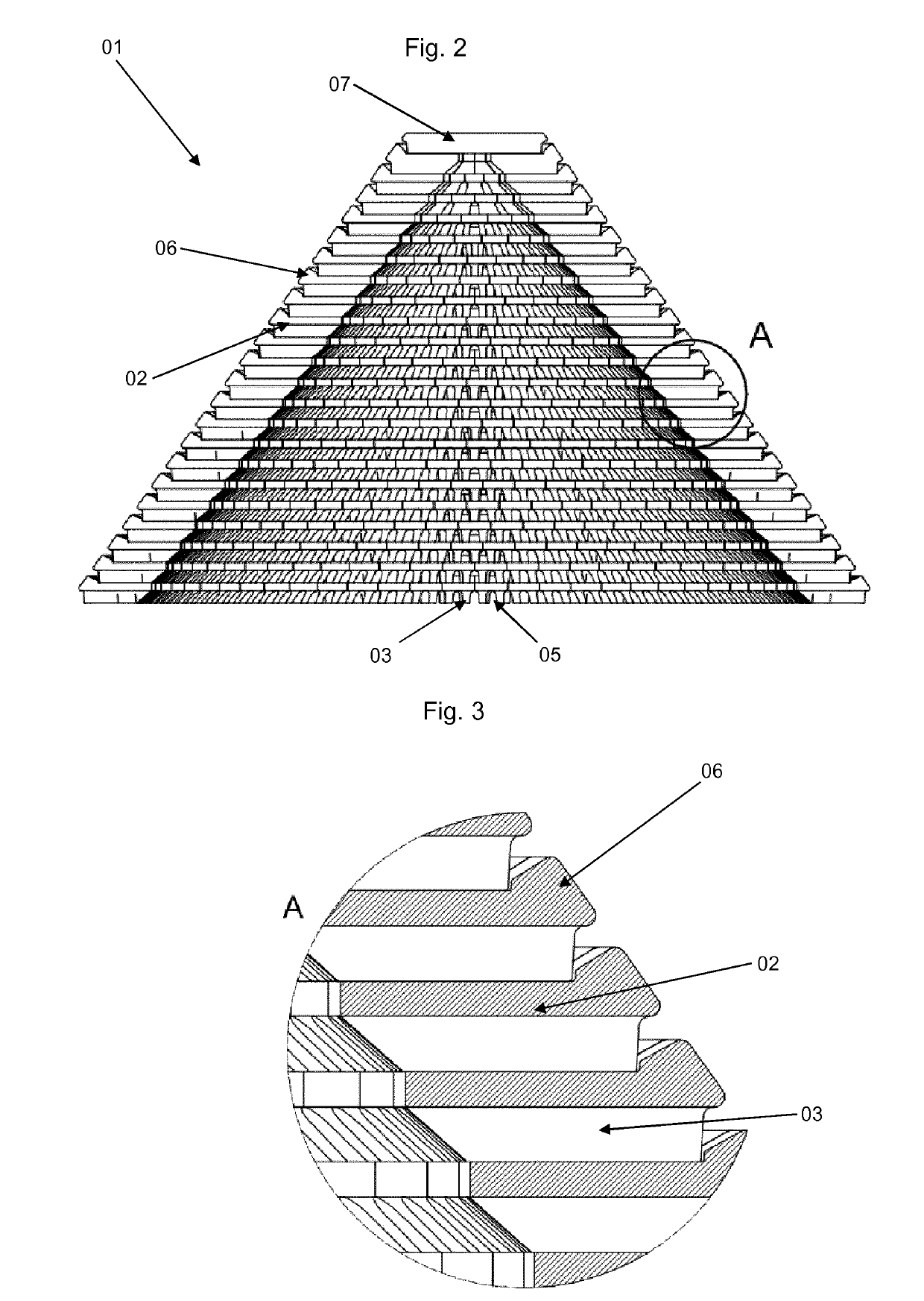
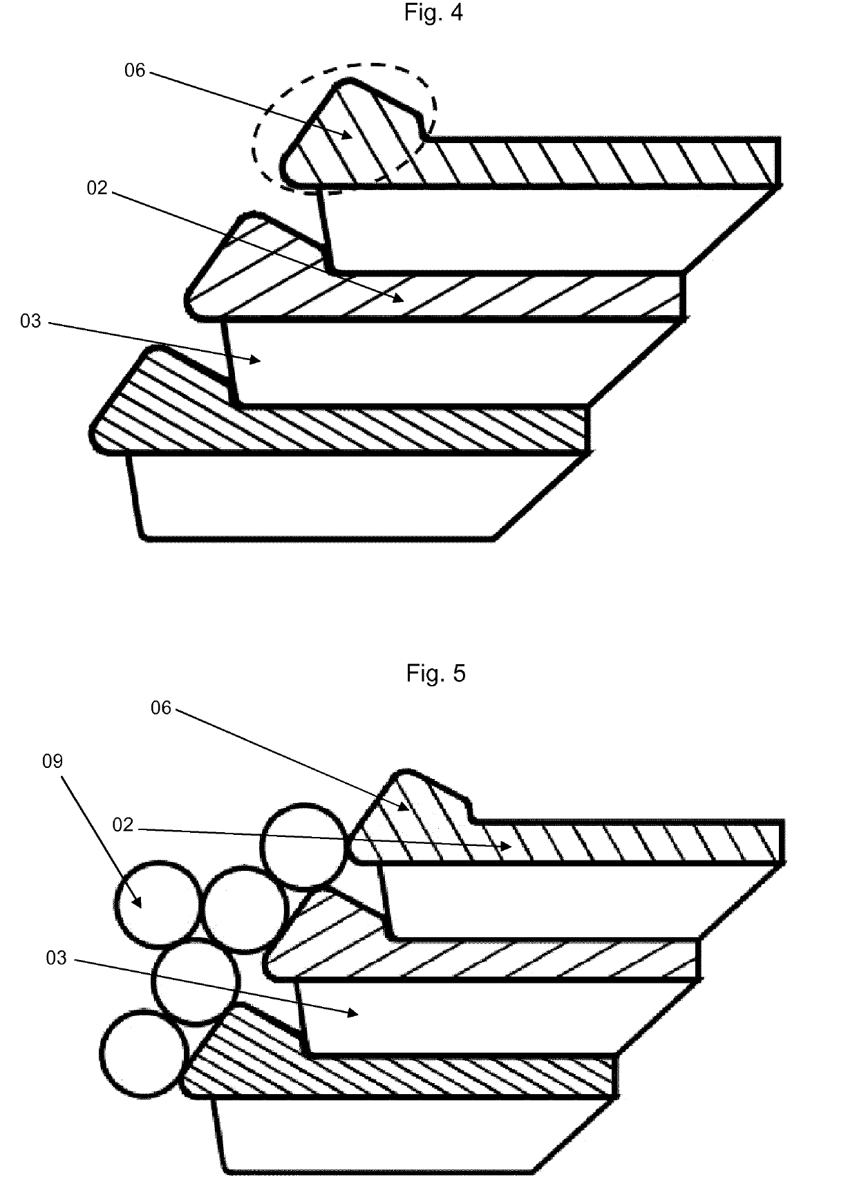
[0044]FIG. 1 shows a catalyst support system 01 to be arranged in the lower part of a chemical reactor (not shown) above and around an opening (not shown) of the reactor. The reactor is partly filled with catalyst (not shown), which is arranged above and possibly also around the catalyst support system. The catalyst support system guards the reactor opening from catalyst entering or exiting the reactor opening. In the embodiment shown, the catalyst support system comprises a plurality of bricks 02 arranged in layers with circular shape. The layers are arranged on top of each other, each circular layer has a smaller diameter than the layer it is arranged on top of, whereby the total catalyst support system obtains a cone-like shape. As shown, the top of the catalyst support system may comprise a flat mono block 07, to close the top of the cone, so no catalyst may enter. Depending on the design demands for the catalyst support system, the cone height may be varied by varying the diame...


PUM


Abstract

The invention relates to a chemical reactor comprising at least one catalyst support system and anti-blocking means arranged around and above a reactor opening, which prevents catalyst or other reactor parts to enter or exit a reactor opening.

Description

FIELD OF THE INVENTION[0001]The invention relates to a chemical reactor comprising a catalyst. More specifically, the invention relates to a catalyst support system arranged in the lower part of the chemical reactor to prevent the catalyst from entering and / or exiting the reactor through one or more process fluid openings in the reactor and it relates to arranging the catalyst support system with high strength.BACKGROUND[0002]Syngas is a mixture of hydrogen and carbon monoxide and it is produced by conversion of methane and other hydrocarbons with steam over a steam reforming catalyst through the steam methane reforming process in one form or another. In ammonia production tubular reforming is combined with secondary reforming and air is added to the secondary reformer to combust residual methane from the primary reformer and to adjust the syngas ratio to achieve the H2 / N2 ratio of approx. 3.0 for the ammonia synthesis. When N2 is an undesired constituent in syngas, pure oxygen can ...

Claims


Application Information

Patent Timeline
IPC IPC(8): B01J8/00B01J8/02
CPCB01J8/0085B01J2208/00884B01J8/0264Y02P20/52B01J8/02
Inventor HANSEN, ANDERS HELBOCHRISTENSEN, THOMAS SANDAHIJØRGENSEN, MAGNUS MØLLERLANSEN, JOHANNES RUBEN
Owner HALDOR TOPSOE AS
Why Eureka
Try Eureka