System and method for calibrating a surgical instrument

a surgical instrument and system technology, applied in the field of system and method for calibrating surgical instruments, can solve problems such as the loss of effectiveness of the control system

Active Publication Date: 2017-08-29
TYCO HEALTHCARE GRP LP
View PDF237 Cites 824 Cited by
  • Summary
  • Abstract
  • Description
  • Claims
  • Application Information

AI Technical Summary

Problems solved by technology

If the components are not properly calibrated, errors may occur in the operation of the surgical instrument and consequently the control system may lose its effectiveness.

Method used


Image

  • System and method for calibrating a surgical instrument
  • System and method for calibrating a surgical instrument
  • System and method for calibrating a surgical instrument

Examples


Embodiment Construction

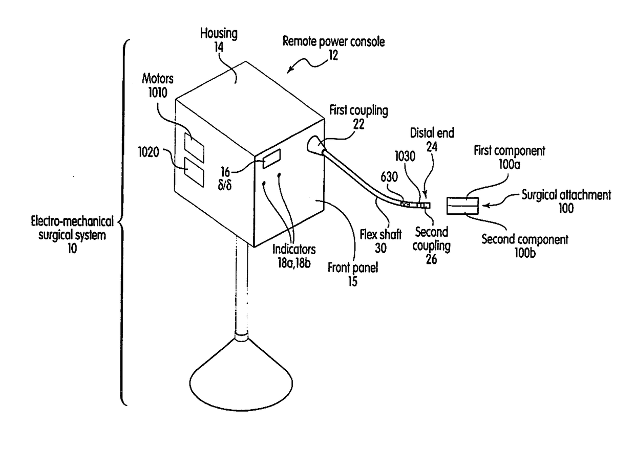
[0022]FIG. 1 is a perspective view of an electro-mechanical surgical system 10, according to one example embodiment of the present invention. The electro-mechanical surgical system 10 may include, for example, a remote power console 12, which includes a housing 14 having a front panel 15. Mounted on the front panel 15 are a display device 16 and indicators 18a, 18b. A flexible shaft 20 may extend from the housing 14 and may be detachably secured thereto via a first coupling 22. The distal end 24 of the flexible shaft 20 may include a second coupling 26 adapted to detachably secure a surgical instrument 100, e.g., a surgical attachment, to the distal end 24 of flexible shaft 20. Alternatively, the distal end 24 of the flexible shaft 20 may be adapted to fixedly secure the surgical instrument 100 to the distal end 24 of flexible shaft 20. The surgical instrument 100 may be, for example, a surgical stapler, a surgical cutter, a surgical stapler-cutter, a linear surgical stapler, a line...


PUM


Abstract

A calibration system for a surgical instrument. The calibration system includes an actuator, such as a motor system and a flexible shaft. The calibration system also includes a surgical instrument actuatable by the actuator. The calibration system also include calibration data corresponding to the surgical instrument. A processor is configured to process the calibration data for determining a position of the surgical instrument. The calibration system may include a sensor configured to provide a signal corresponding to a movement of the actuator, the processor being further configured to process the signal for determining a position of the surgical instrument.

Description

CLAIM OF PRIORITY[0001]This application is a Continuation Application which claims the benefit of and priority to U.S. patent application Ser. No. 10 / 309,532, filed Dec. 4, 2002, which claims the benefit of and priority to U.S. Provisional Patent Application Ser. No. 60 / 337,544, filed on Dec. 4, 2001, each of which is expressly incorporated herein by reference in its entirety.CROSS-REFERENCE TO RELATED APPLICATIONS[0002]This application incorporates by reference in its entirety U.S. application Ser. No. 09 / 723,715, filed on Nov. 28, 2000, now U.S. Pat. No. 6,793,652, U.S. application Ser. No. 09 / 836,781, filed on Apr. 17, 2001, now U.S. Pat. No. 6,981,941, U.S. application Ser. No. 09 / 887,789, filed on Jun. 22, 2001, now U.S. Pat. No. 7,032,798, U.S. application Ser. No. 09 / 324,451, filed on Jun. 2, 1999, which issued as U.S. Pat. No. 6,315,184 on Nov. 13, 2002, U.S. application Ser. No. 09 / 324,452, filed on Jun. 2, 1999, which issued as U.S. Pat. No. 6,443,973 on Sep. 3, 2002, U.S....

Claims


Application Information

Patent Timeline
Patent Type & Authority Patents(United States)
IPC IPC(8): A61B17/068A61B90/98A61B5/0215A61B17/072A61B17/115A61B17/00A61B90/90A61B19/00
CPCA61B17/068A61B90/98A61B5/02156A61B17/072A61B17/07207A61B17/115A61B90/90A61B2017/0046A61B2017/00477A61B2017/00725
Inventor WHITMAN, MICHAEL P.
Owner TYCO HEALTHCARE GRP LP
Why Eureka
Try Eureka