Metal nailer with adjustable curvature

a nailer and curvature technology, applied in the field of building structures, can solve the problems of not including the attachment of both the upper and lower members in the above-mentioned patents

Active Publication Date: 2017-11-14
METAL ERA LLC
View PDF10 Cites 0 Cited by
  • Summary
  • Abstract
  • Description
  • Claims
  • Application Information

AI Technical Summary

Benefits of technology

[0007]An upward bent fold with a 45 degree included angle is formed in a center of each first and second lower opening. However, other values of included angles may also be used. The upward bent fold includes a first sidewall bent strip a second sidewall bent strip and a base bent strip. A height of the first and second sidewall bent strips is less than half of a height of a first lower sidewall and a second lower sidewall. A height of the base bent strip is less than half of a height of the first and second lower sidewalls. A width of the base strip is greater than a width of the first or second lower openings. The first and second edges of the lower strip are bent at a substantially 90 degree angle relative to a middle portion of the lower strip to form a U-shape. The first lower sidewall, the second lower sidewall and a lower base portion are formed from the bending.
[0008]The upper member includes an upper strip of material. The upper member includes all the features of the lower member, except that the lower fastener openings are replaced with fastener clearance openings to allow a fastener to be installed with a tool. The upper member is inserted into the lower member, such that one of the first and second upper sidewalls are inserted between the first and second lower sidewalls and moved horizontally, such that the first and second upper sidewalls contact the first and second lower sidewalls. A plurality of fasteners, such as rivets or the like are used to secure the first upper sidewall to the first lower sidewall and the second lower sidewall to the second upper sidewall. The upper member allows fascia materials to be secured to a top surface thereof.

Problems solved by technology

However, neither of the above patents include attachment to both an upper and lower member.

Method used


Image

  • Metal nailer with adjustable curvature
  • Metal nailer with adjustable curvature
  • Metal nailer with adjustable curvature

Examples


Embodiment Construction

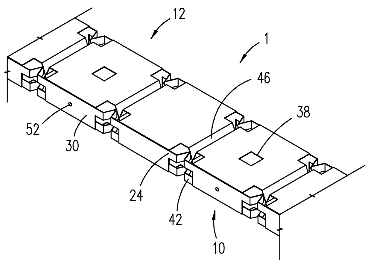
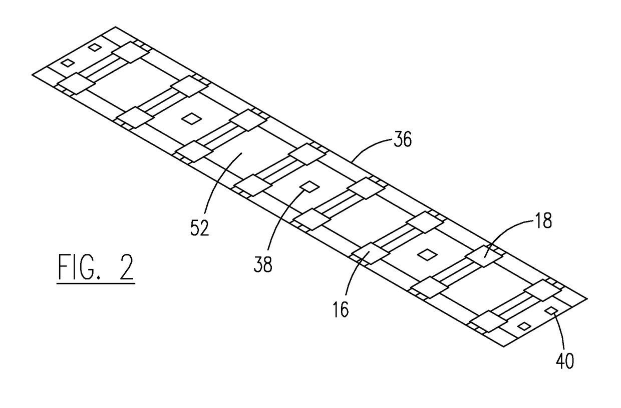
[0023]With reference now to the drawings, and particularly to FIG. 9, there is shown a perspective view of a metal nailer with adjustable curvature 1. With reference to FIG. 5, the metal nailer with adjustable curvature 1 preferably includes a lower member 10 and an upper member 12. With reference to FIG. 1, the lower member 10 includes a lower strip of material 14. A first plurality of lower openings 16 are formed adjacent a first edge of the lower strip and a second plurality lower openings 18 are formed adjacent a second edge of the lower strip 14. The plurality of first and second lower openings 16, 18 occur at a set distance from each other in a series. The plurality of first and second openings 16, 18 preferably have a rectangular shape, but other shapes could also be used. A fastener opening 20 is formed in substantially a center of two adjacent first lower openings 16 and two adjacent second lower openings 18. Two lower fastener openings 20 are formed in opposing ends of eac...


PUM


Abstract

A metal nailer with adjustable curvature preferably includes an upper member and a lower member. The upper and lower members start as strips of material. A plurality of first openings are formed adjacent a first edge of each strip. A plurality of second openings are formed adjacent a second edge of each strip. A plurality of fastener openings are formed in the lower strip and a plurality of fastener clearance openings in the upper strip. An upward bent fold is formed in a center of each of the plurality of first and second openings. First and second edges of the strips are bent to form a U-shape. The upper member is inserted into the lower member. The upper and lower members are attached to each other with a plurality of fasteners. The metal nailer with adjustable curvature may be bent in horizontal and/or vertical planes.

Description

BACKGROUND OF THE INVENTION[0001]1. Field of the Invention[0002]The present invention relates generally to building structures and more specifically to a metal nailer with adjustable curvature, which allows a curved coping or fascia system to be attached to an edge of a building.[0003]2. Discussion of the Prior Art[0004]U.S. Pat. No. 6,237,301 to Paradis discloses a flexible runner. U.S. Pat. No. 7,458,188 to Mears discloses a structural alignment member. However, neither of the above patents include attachment to both an upper and lower member.[0005]Accordingly, there is a clearly felt need in the art for a metal nailer with adjustable curvature, which allows a coping or fascia system with a curve in horizontal and / or vertical planes to be attached to an edge of a building.SUMMARY OF THE INVENTION[0006]The present invention provides a metal nailer with adjustable curvature, which allows a curved coping or fascia system to be attached to a curved edge of a building. The metal nailer...

Claims


Application Information

Patent Timeline
Patent Type & Authority Patents(United States)
IPC IPC(8): E04B2/00E04B2/62
CPCE04B2/62E04B2/7457E04B2002/7481
Inventor INZEO, JOSEPH A.KASTNER, PETER H.
Owner METAL ERA LLC
Why Eureka
Try Eureka