Display device with adjustable curvature

a display device and curvature technology, applied in the direction of identification means, electrical apparatus casings/cabinets/drawers, instruments, etc., can solve the problems of not being able to adapt the display curve to the viewer, and the specific curvature designed for the liquid crystal display panel may not be the most suitable display curvature for the viewer

Active Publication Date: 2019-08-13
AU OPTRONICS CORP
View PDF42 Cites 0 Cited by
  • Summary
  • Abstract
  • Description
  • Claims
  • Application Information

AI Technical Summary

Benefits of technology

[0007]The display devices according to various embodiments of the present invention can adjust a curvature of a display panel by different extents of linear movement or rotation base on a position and an angle of a viewer. Therefore, an appropriate curvature can be provided for a viewer correspondingly. Furthermore, when a viewer does not view the display panel from a position relative to the center thereof, the display device according to the embodiment of the present invention can provide a more appropriate display effect for the viewer by differently adjusting the curvatures of the respective parts of the display panel.

Problems solved by technology

However, even if the display panel has flexibility and can be bent with a defined curvature, when a distance and an angle of a viewer relative to the display panel are changed, the display panel cannot display image with an optimum angle accordingly.
For example, in the case that the flexibility is applied to a liquid crystal display panel, since the display effect of the liquid crystal display panel will be changed when a viewing angle is changed, the specific curvature designed for the liquid crystal display panel may not be the most suitable display curvature for the viewer.

Method used


Image

  • Display device with adjustable curvature
  • Display device with adjustable curvature
  • Display device with adjustable curvature

Examples


Embodiment Construction

[0019]Various embodiments will be described as follows, and a person of ordinary skill in the art can easily understand the spirit and principle of the present invention with reference to the accompanied drawings. However, although some specific embodiments are described herein, they are only exemplary, and do not mean limitation or exhaustion in any aspect. Therefore, a person of ordinary skill in the art can make various changes and amendments to the present invention apparently without departing from the spirit and principle of the present invention.

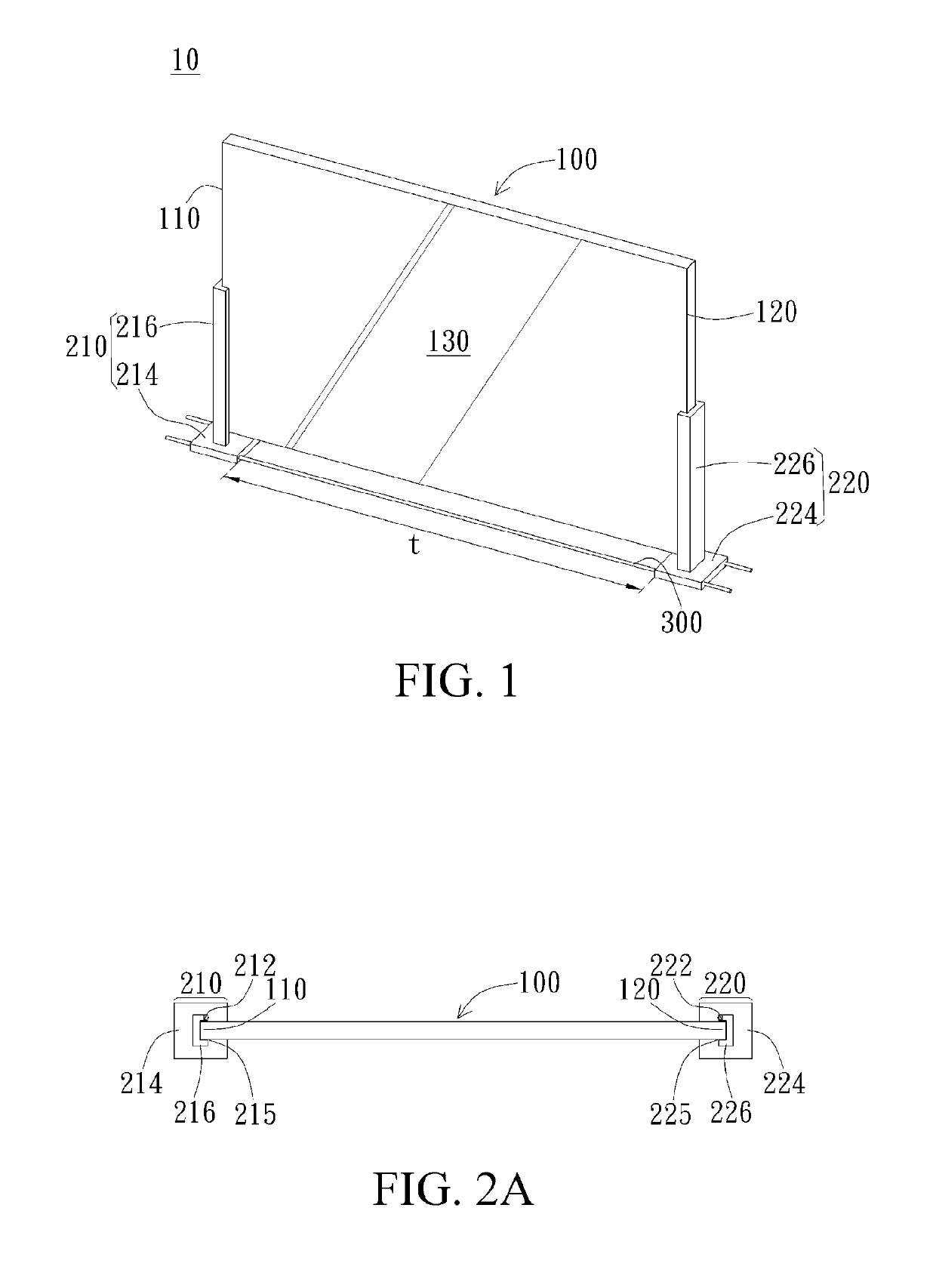
[0020]The display device according to one embodiment of the present invention will be described with reference to FIGS. 1 to 3.

[0021]First, with reference to FIG. 1, the display device 10 includes a display panel 100, a first holder 210, and a second holder 220. The display panel 100 has a first side 110 and a second side 120 that are opposite to each other, and a display surface 130 between the first side 110 and the second side 120....


PUM

PropertyMeasurementUnit
lengthaaaaaaaaaa
lengthaaaaaaaaaa
lengthaaaaaaaaaa

Abstract

The present invention provides a display device including a display panel, a first holder, and a second holder. The display panel includes a first side and a second side opposite to each other, and a display surface between the first side and the second side. The first holder is extended along the first side and holds the first side, and the second holder is extended along the second side and holds the second side. In the display device, the first holder and the second holder are capable of moving linearly relative to each other, so as to drive the first side and the second side to move relative to each other and force the display panel to bend. Further, the first holder and the second holder are capable of respectively driving the first side and the second side to rotate.

Description

BACKGROUND[0001]Technical Field[0002]The present invention relates to a display device. More specifically, the present invention relates to a display device with an adjustable curvature.[0003]Related Art[0004]Nowadays, along with development and popularity of various electronic devices, demand for display panels is growing. Also, since electronic devices are developed to be lighter and thinner, more and more attention is paid to flexible display panels. Specifically, a flexible display panel capable of being bent is required to satisfy use demand in different environments. However, even if the display panel has flexibility and can be bent with a defined curvature, when a distance and an angle of a viewer relative to the display panel are changed, the display panel cannot display image with an optimum angle accordingly. For example, in the case that the flexibility is applied to a liquid crystal display panel, since the display effect of the liquid crystal display panel will be chang...

Claims


Application Information

Patent Timeline
Patent Type & Authority Patents(United States)
IPC IPC(8): H05K5/00G02F1/13G02F1/1333H05K5/02H01L51/00H01L51/52
CPCG02F1/1323G02F1/133305G02F1/133308H05K5/0017H05K5/0217H01L2251/5338G02F2001/133314G02F2201/58H01L51/0097H01L51/5237F16M11/2085F16M11/22G09F9/301G09F9/35F16M2200/08G02F1/13336G02F1/133314H10K50/84H10K77/111H10K2102/311
Inventor WANG, WEI-SHYANG
Owner AU OPTRONICS CORP
Why Eureka
Try Eureka