Device and method for staggered extrusion forming of curved components
A technology of extrusion forming and staggering, applied in the direction of metal extrusion dies, etc., can solve the problems of difficult manufacturing process, difficult quality assurance, high cost, etc., and achieve the effect of rich variety, diversified application fields and low cost
- Summary
- Abstract
- Description
- Claims
- Application Information
AI Technical Summary
Problems solved by technology
Method used
Image
Examples
specific Embodiment approach 1
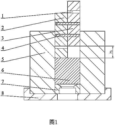
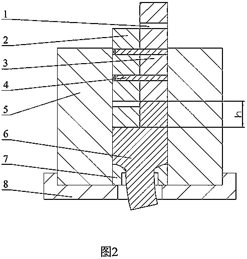
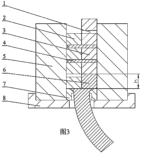
[0037] Specific implementation mode one: combine Figure 1~Figure 3This embodiment will be described. In this embodiment, the punch is designed as a left-right symmetrical two-part structure. This embodiment includes: a positioning hole 1 , a left punch 2 , a right punch 3 , a positioning pin 4 , an extrusion barrel 5 , a blank 6 , a mandrel 7 and a base 8 . This embodiment is completed by the following steps: 1. Make the punch into two parts, the left punch 2 and the right punch 3; 2. Stagger the left punch 2 and the right punch 3 according to the curvature of the required bending member. The distance h is placed, and the positioning pin 4 is inserted into the positioning hole 1 between the two punches to fix it; 3. Fix the base 8 on the press workbench; 4. Place the extrusion cylinder 5 above the base 8; 5. 1. Put the mandrel 7, the blank 6, the combination of the left punch 2 fixed with the positioning pin 4 and the right punch 3 in the extrusion cylinder 5 in turn; six, l...
specific Embodiment approach 2
[0038] Specific implementation mode two: combination Figure 4~Figure 6 Describe this embodiment. The punch in this embodiment is designed as a three-part structure. This embodiment includes: positioning hole 1, left punch 2, right punch 3, positioning pin 4, extrusion barrel 5, blank 6, and mandrel 7 And base 8, middle punch 9. This embodiment is completed by the following steps: 1. Set the left punch 2, the middle punch 9 and the right punch 3 at staggered distances according to the curvature of the required bending parts, and the adjacent punches are staggered by a certain distance h / 2. Fix it with positioning pin 4; 2. Fix the base 8 on the press table; 3. Place the extrusion cylinder 5 above the base 8; 4. Put the core mold 7 into the extrusion cylinder 5 in sequence , blank 6, the combination of left punch 2, middle punch 9 and right punch 3 fixed by positioning pin 4; five, the combined punch is loaded, left punch 2, middle punch 9 and right punch The head 3 contacts...
specific Embodiment approach 3
[0039] Specific implementation mode three: combination Figure 7~Figure 9 Describe this embodiment. The punch in this embodiment is designed as a three-part structure. This embodiment includes: positioning hole 1, left punch 2, right punch 3, positioning pin 4, extrusion barrel 5, blank 6, and mandrel 7 And base 8, middle punch 9. Wherein, the stagger amount between the left punch 2 and the middle punch 9 is h / 2. Other connection relationships are the same as those in the second embodiment.
PUM
 Abstract
Description
Claims
Application Information
 - R&D
- Intellectual Property
- Life Sciences
- Materials
- Tech Scout
- Unparalleled Data Quality
- Higher Quality Content
- 60% Fewer Hallucinations
Browse by: Latest US Patents, China's latest patents, Technical Efficacy Thesaurus, Application Domain, Technology Topic, Popular Technical Reports.
© 2025 PatSnap. All rights reserved.Legal|Privacy policy|Modern Slavery Act Transparency Statement|Sitemap|About US| Contact US: help@patsnap.com


