Micro speaker with capacitors formed by conductive cover and diaphragm

a capacitor and diaphragm technology, applied in the field of micro speakers, can solve the problem that the method cannot detect the real-time amplitude of the diaphragm correctly

Inactive Publication Date: 2017-11-14
AAC TECH PTE LTD
View PDF3 Cites 8 Cited by
  • Summary
  • Abstract
  • Description
  • Claims
  • Application Information

AI Technical Summary

Benefits of technology

[0003]The present invention provides an improved method or solution to detect the real-time amplitude of the diaphragm of a micro speaker.

Problems solved by technology

This type of method cannot detect the real-time amplitude of the diaphragm correctly.

Method used


Image

  • Micro speaker with capacitors formed by conductive cover and diaphragm
  • Micro speaker with capacitors formed by conductive cover and diaphragm

Examples


Embodiment Construction

[0007]The present invention will hereinafter be described in detail with reference to an exemplary embodiment. To make the technical problems to be solved, technical solutions and beneficial effects of present disclosure more apparent, the present disclosure is described in further detail together with the Fig.s and the embodiment. It should be understood the specific embodiment described hereby is only to explain this disclosure, not intended to limit this disclosure.

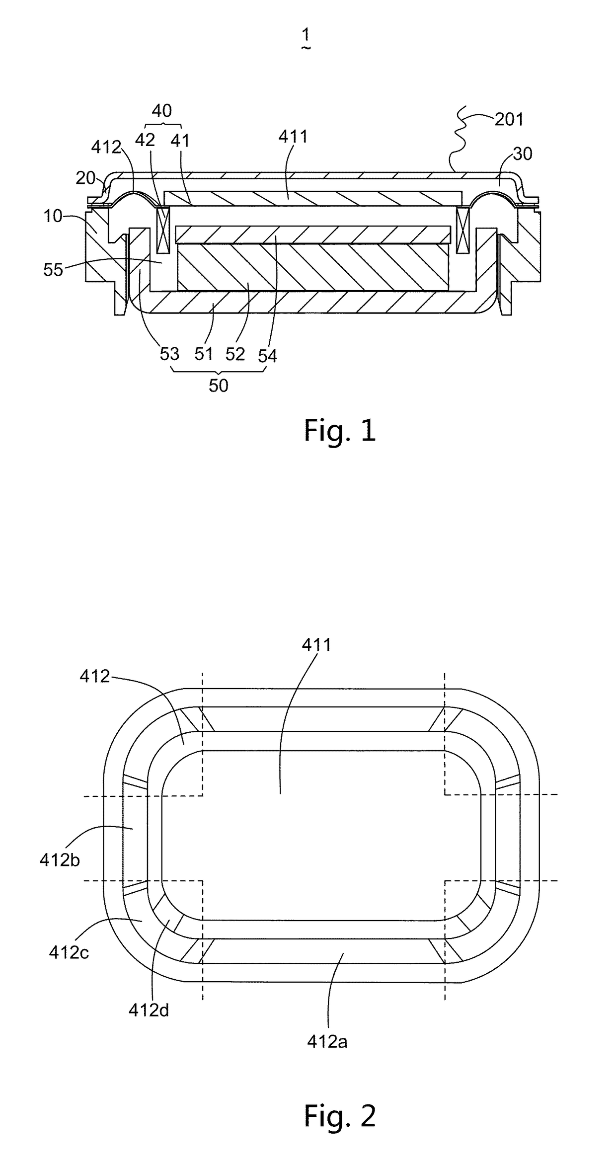
[0008]Referring to FIG. 1, a micro speaker 1 in accordance with a first embodiment of the present disclosure comprises a frame 10, a conductive front cover 20 engaging with the frame 10, a receiving space 30 formed by the frame 10 and the conductive front cover 20, a vibration system 40 and a magnetic circuit system 50 respectively received in the receiving space 30.

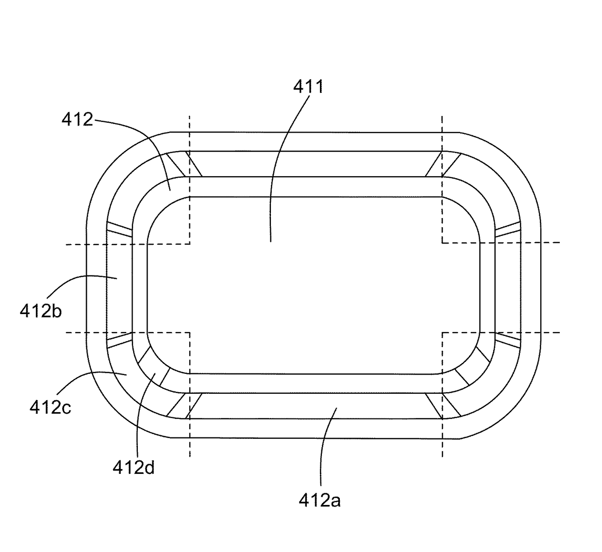
[0009]The vibration system 40 includes a diaphragm 41 and a voice coil 42 driving the diaphragm 41 to generate sounds. The diaphragm 41 includes a conducti...


PUM


Abstract

A micro speaker is disclosed. The micro speaker includes a diaphragm and a voice coil for driving the diaphragm, the diaphragm including a conductive dome a suspension surrounding the conductive dome; a conductive front cover located adjacent to and keeping a distance from the conductive dome; and a capacitor formed by the conductive dome and the conductive front cover for outputting electrical signals according to vibrations of the diaphragm and for detecting real-time replacement of the diaphragm.

Description

FIELD OF THE INVENTION[0001]The present invention relates to the field of electroacoustic transducers, more particularly to a micro speaker.DESCRIPTION OF RELATED ART[0002]The normal or typical method to detect the amplitude of the diaphragm of a speaker is linear estimation method. This type of method cannot detect the real-time amplitude of the diaphragm correctly.[0003]The present invention provides an improved method or solution to detect the real-time amplitude of the diaphragm of a micro speaker.BRIEF DESCRIPTION OF THE DRAWINGS[0004]Many aspects of the embodiments can be better understood with reference to the following drawings. The components in the drawings are not necessarily drawn to scale, the emphasis instead being placed upon clearly illustrating the principles of the present disclosure. Moreover, in the drawings, like reference numerals designate corresponding parts throughout the several views.[0005]FIG. 1 is a cross-sectional view of a micro speaker in accordance w...

Claims


Application Information

Patent Timeline
Patent Type & Authority Patents(United States)
IPC IPC(8): H04R1/00H04R29/00H04R9/06H04R7/12H04R7/18
CPCH04R29/003H04R7/127H04R9/06H04R7/18H04R2307/204H04R1/06
Inventor ZHANG, YANG
Owner AAC TECH PTE LTD
Why Eureka
Try Eureka