
Method and system for superimposing virtual anatomical landmarks on an image

an image and landmark technology, applied in the field of medical imaging and navigation systems, can solve the problems of limiting or even preventing the identification of such anatomical landmarks, poor visibility or even invisible of anatomical landmarks within a region of interest (i.e., in the patient's body), and achieve the effect of accurate and flexible specification of virtual landmarks

Active Publication Date: 2017-12-05
ST JUDE MEDICAL INT HLDG SARL
View PDF155 Cites 12 Cited by
  • Summary
  • Abstract
  • Description
  • Claims
  • Application Information

AI Technical Summary

Benefits of technology

Enhances the visibility of anatomical landmarks, allowing for more accurate navigation during medical procedures by providing a flexible and accurate method to designate virtual landmarks within the body, including in non-tubular organs like the heart chamber.

Problems solved by technology

In the field of medical imaging and navigation, anatomical landmarks within a region of interest (i.e., in a patient's body) are often poorly visible or even invisible on a fluoroscopic image of the region of interest.
This lack of visibility may limit or even prevent identification of such anatomical landmarks by a physician during a medical procedure.

Method used


Image

  • Method and system for superimposing virtual anatomical landmarks on an image
  • Method and system for superimposing virtual anatomical landmarks on an image
  • Method and system for superimposing virtual anatomical landmarks on an image

Examples


Embodiment Construction

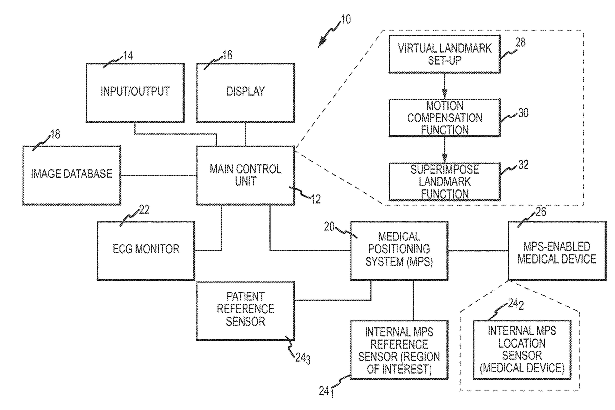
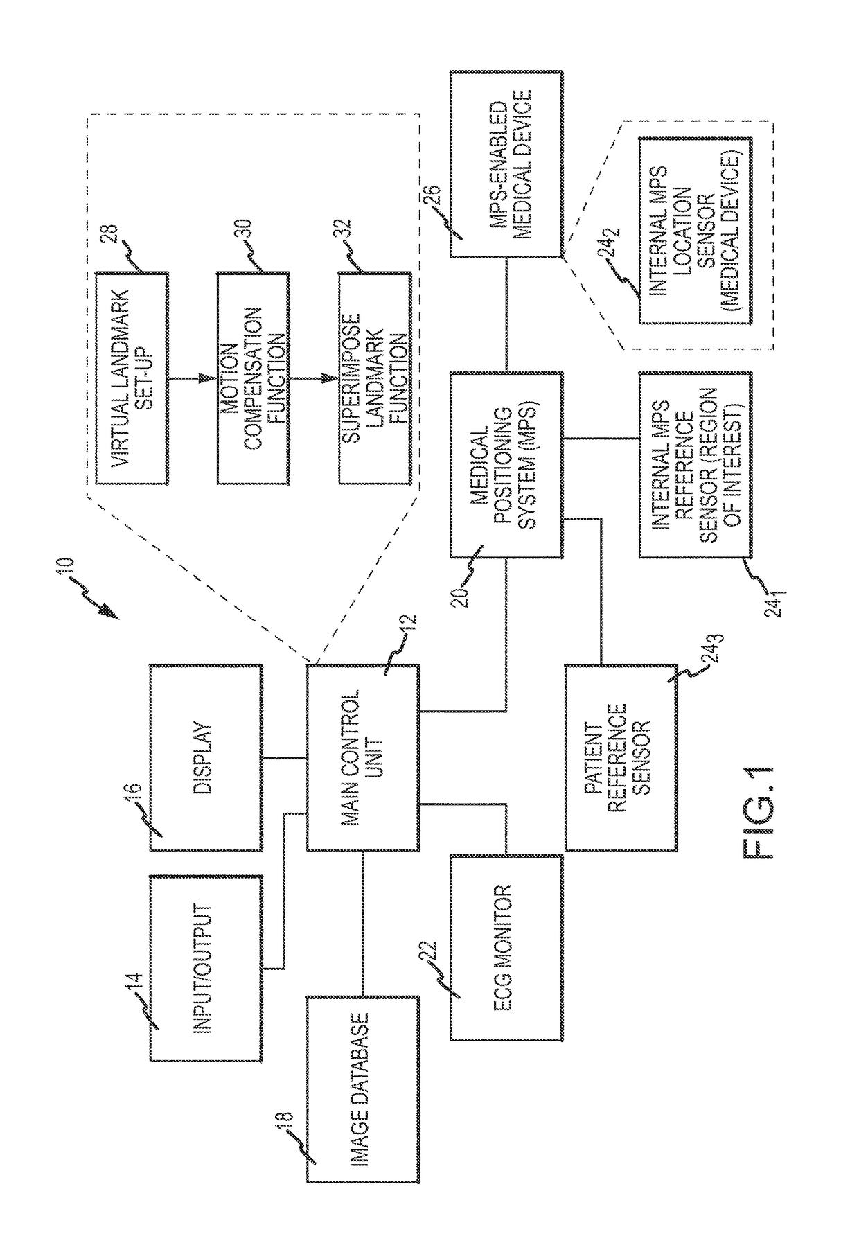
[0019]Referring now to the drawings wherein like reference numerals are used to identify identical components in the various views, FIG. 1 is a diagrammatic view of a system 10 in which aspects of an apparatus and method for superimposing virtual anatomical landmarks on an image may be embodied. It should be understood that while embodiments will be described in connection with a magnetic field-based positioning system in a catheter-lab environment, this is exemplary only and not limiting in nature.

[0020]As described in the Background, anatomical landmarks within a region of interest in a patient's body are often only poorly visible or even invisible on a fluoroscopic image of the region. This lack of visibility may encumber the identification of the landmark by a physician during a medical procedure. There is therefore a desire to improve the visibility of an anatomical landmark, whether on live fluoroscopic images or still or cine-loops captured at an earlier time. Embodiments of ...


PUM


Abstract

A system for superimposing virtual anatomical landmarks on an image includes a medical positioning system (MPS) for producing location readings with respect to points within a region of interest in accordance with an output of a location sensor disposed in a medical device. A coordinate system of the MPS is registered with an image coordinate system. A control unit receives a signal from a user to record a location reading when the medical device is at a desired point in the region of interest where the user desires to place a virtual landmark, modifies the recorded location reading for motion compensation, transforms the motion-compensated location reading from the MPS coordinate system to the image coordinate system to produce a target location, and then superimposes a representation of the virtual landmark on the image at the target location.

Description

CROSS-REFERENCE TO RELATED APPLICATIONS[0001]This application is a continuation-in-part (CIP) of U.S. application Ser. No. 11 / 233,420 filed Sep. 16, 2005 (the '420 application), now U.S. Pat. No. 8,442,618, which is a continuation-in-part (CIP) of U.S. application Ser. No. 10 / 986,567 filed Nov. 10, 2004 (the '567 application), now U.S. Pat. No. 9,572,519, which is a continuation-in-part (CIP) of U.S. application Ser. No. 10 / 938,395 filed on Sep. 9, 2004 (the '395 application), now U.S. Pat. No. 7,778,688. The '420 application, the '567 application, and the '395 application are hereby incorporated by reference as though fully set forth herein. As to U.S. application Ser. No. 09 / 949,160, filed on Sep. 7, 2001 (the '160 application), now U.S. Pat. No. 7,343,195, U.S. application Ser. No. 09 / 782,528, filed on Feb. 13, 2001 (the '528 application), now U.S. Pat. No. 7,386,339, and U.S. application Ser. No. 09 / 314,474, filed on May 18, 1999 (the '474 application), now U.S. Pat. No. 6,233,4...

Claims


Application Information

Patent Timeline
Patent Type & Authority Patents(United States)
IPC IPC(8): A61B5/05A61B6/12A61B6/04A61B5/00A61B5/06A61B8/08A61B8/00A61B8/12A61B5/01A61B5/0456A61B6/00A61B17/00A61B34/20A61B90/00A61B34/10A61B5/352
CPCA61B5/06A61B5/706A61B5/7475A61B6/0492A61B6/12A61B6/465A61B6/466A61B6/469A61B6/5247A61B8/0833A61B8/12A61B8/40A61B8/5238A61B34/20A61B5/062A61B2090/3958A61B5/015A61B5/0456A61B5/066A61B5/7425A61B6/4441A61B34/10A61B2017/00243A61B2017/00703A61B2034/2051A61B2034/2072A61B2090/364A61B2090/365A61B2090/376A61B5/352
Inventor COHEN, AMITSTROMMER, GERAEICHLER, UZI
Owner ST JUDE MEDICAL INT HLDG SARL
Learn More