Tile leveling structure

Inactive Publication Date: 2018-01-23
PLUS CRAFT INDAL
View PDF9 Cites 20 Cited by
  • Summary
  • Abstract
  • Description
  • Claims
  • Application Information

AI Technical Summary

Benefits of technology

The present invention is a tile leveling structure with a leveling member that rests on the tiles while pressing them to level them. The structure is easy to operate with a manual labor force and without the need for tools. This makes it convenient for operators to level tiles. The technical effect of the invention is to provide a simple and efficient solution for leveling tiles.

Problems solved by technology

However, the operator has to operate the leveling member 20 by aid of a hand tool, thereby causing inconvenience to the operator when operating the conventional tile leveling structure.
In addition, the operator needs to carry the hand tool for operating the conventional tile leveling structure, thereby causing a burden to the operator.

Method used


Image

  • Tile leveling structure
  • Tile leveling structure
  • Tile leveling structure

Examples


Embodiment Construction

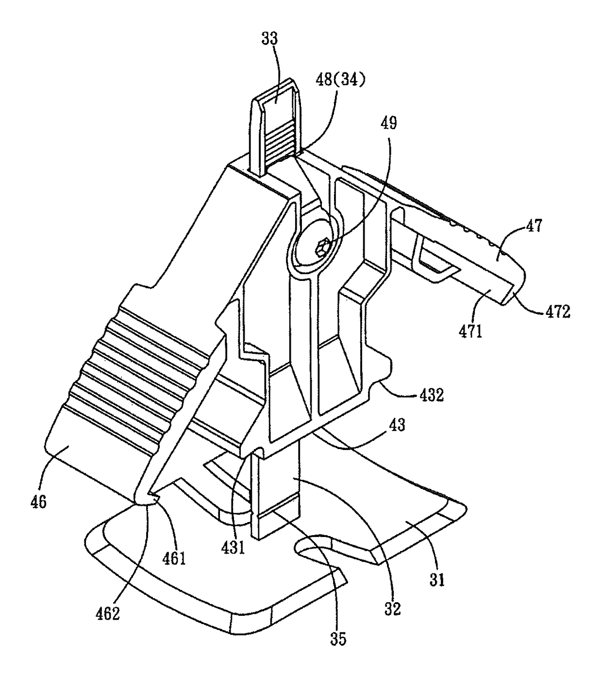
[0020]Referring to the drawings and initially to FIGS. 3-6, a tile leveling structure in accordance with the preferred embodiment of the present invention comprises a fixture 30 and a leveling member 40 mounted on the fixture 30.

[0021]The fixture 30 includes a base 31, an adjusting plate 32 integrally formed on and extending upward from the base 31, and a oneway toothed rack 34 mounted on the adjusting plate 32 and located adjacent to a top end 33 of the adjusting plate 32. The base 31 and the adjusting plate 32 of the fixture 30 have a connection formed with a breaking point 35.

[0022]The leveling member 40 is provided with a passage 41, and the adjusting plate 32 of the fixture 30 passes through the passage 41 of the leveling member 40. The passage 41 extends longitudinally through a whole length of the leveling member 40. The leveling member 40 has a bottom provided with a pressing face 43 which has a first side provided with a first locking portion 431 and a second side provided ...


PUM


Abstract

A tile leveling structure includes a fixture and a leveling member mounted on the fixture. The fixture includes a base, an adjusting plate extending upward from the base, and a oneway toothed rack mounted on the adjusting plate. The base and the adjusting plate have a connection formed with a breaking point. The leveling member is provided with a passage through which the adjusting plate passes. The leveling member has a bottom provided with a pressing face is provided with a first locking portion and a second locking portion. The leveling member is provided with a first wing and a second wing. The first wing is provided with a first hook which is provided with a first abutting face. The second wing is provided with a second hook which is provided with a second abutting face.

Description

BACKGROUND OF THE INVENTION[0001]1. Field of the Invention[0002]The present invention relates to a leveling structure and, more particularly, to a tile leveling structure.[0003]2. Description of the Related Art[0004]A conventional tile leveling structure in accordance with the prior art shown in FIGS. 1 and 2 comprises a base 10, an adjusting plate 11 integrally formed on and extending upward from the base 10, a oneway toothed rack 13 mounted on the adjusting plate 11 and located adjacent to the top end 12 of the adjusting plate 11, and a leveling member 20 movably mounted on the adjusting plate 11. The base 10 and the adjusting plate 11 have a connection formed with a breaking point 14. The adjusting plate 11 is made of plastic material with resilience and flexibility. The leveling member 20 has a hollow inside and has an upper end provided with an operation face 21 and a lower end provided with an abutting face 22. The operation face 21 of the leveling member 20 is provided with a...

Claims


Application Information

Patent Timeline
IPC IPC(8): E04F21/00E04F21/20
CPCE04F21/20E04F21/0092
Inventor CHEN, TIMMY
Owner PLUS CRAFT INDAL
Why Eureka
Try Eureka