Sawing machine

Inactive Publication Date: 2008-05-22
DURQ MACHINERY
View PDF7 Cites 9 Cited by
  • Summary
  • Abstract
  • Description
  • Claims
  • Application Information

AI Technical Summary

Benefits of technology

[0007]The present invention has been accomplished under the circumstances in view. It is the main object of the present invention to provide a sawing machine, which facilitates force exertion and enhances the operational convenience.
[0010]Before operating the sawing machine, the user can adjust the handle to the best angle convenient for applying the force, so that the user can operate the sawing machine conveniently and easily.

Problems solved by technology

However, when moving the handle downwards to lower the cutting disk during a cutting operation of the miter saw, the operator cannot easily force the handle downward to drive movement of the cutting disk.
Therefore, this design of miter saw is still not convenient in operation.

Method used


Image

  • Sawing machine
  • Sawing machine
  • Sawing machine

Examples


Embodiment Construction

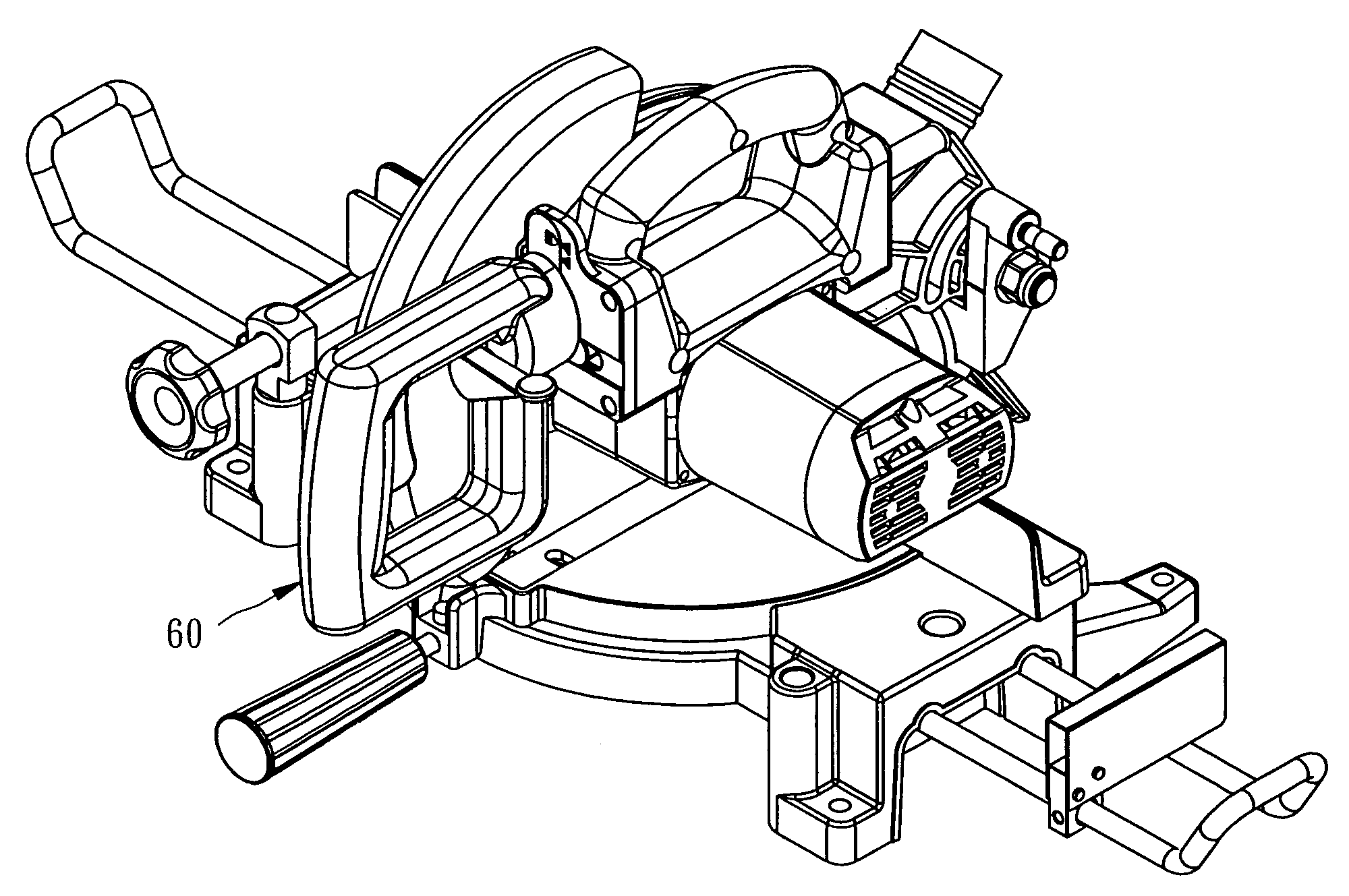
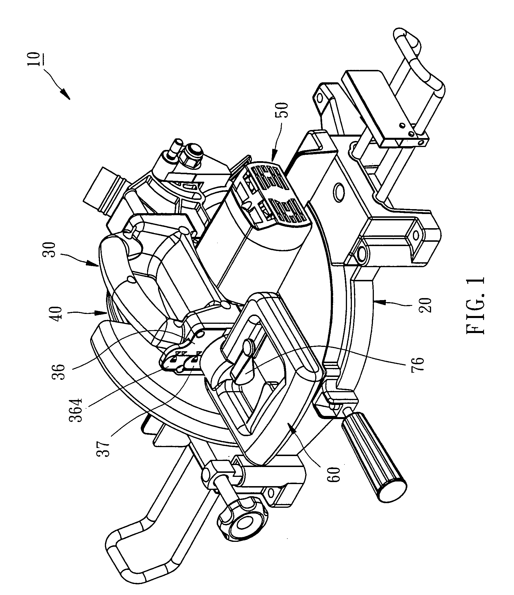
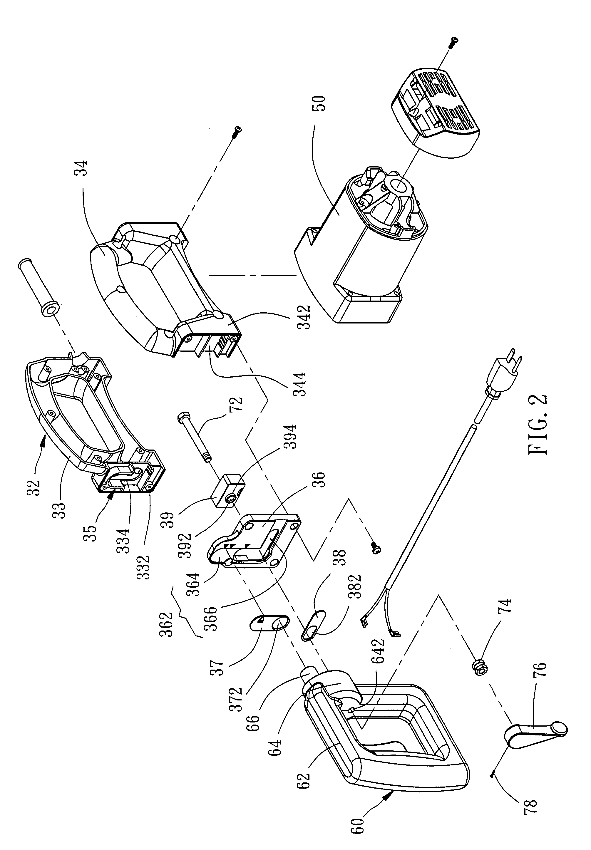
[0018]Referring to FIG. 13, a sawing machine 10 in accordance with a preferred embodiment of the present invention is composed of a base 20, a saw arm assembly 30, a saw blade 40, a motor 50, a handle 60, and a locking mechanism 70.

[0019]The base 20 is a flat circular block member for placing a workpiece thereon for being cut.

[0020]The saw arm assembly 30 includes a body 32 formed of two half shells 33 and 34. The two half shells 33 and 34 abut together. One half shell, namely, the first half shell 33 has one end pivotally connected to the base 20, and the other end provided with a coupling portion 332. The first half shell 33 further has a first groove 334 formed in the coupling portion 332 and extending in a direction perpendicular to the base 20. The second half shell 34 has one end pivotally connected to the base 20, and the other end provided with a coupling portion 342. The second half shell 34 further has a second groove 344 formed in the coupling portion 342 and extending in...


PUM

PropertyMeasurementUnit
Fractionaaaaaaaaaa
Angleaaaaaaaaaa

Abstract

A sawing machine includes a base, a saw arm assembly pivotally connected to the base and having a L-shaped groove defined therein, a saw blade pivotally mounted to the saw arm assembly, a handle pivotally mounted to the L-shaped groove of the saw arm assembly for rotatable movement relative to the saw arm assembly, and a locking mechanism mounted to the handle for locking the handle to the saw arm assembly. Before operation, the handle is adjusted to the best angle that the user can conveniently apply the force, so that the user can operate the sawing machine easily and conveniently.

Description

BACKGROUND OF THE INVENTION[0001]1. Field of the Invention[0002]The present invention relates to a sawing machine and more particularly, to a sawing machine, which allows the operator to easily apply the force to operate the sawing machine conveniently and easily.[0003]2. Description of the Related Art[0004]U.S. Pat. No. 6,658,976, entitled “Ergonomic miter saw handle”, disclosed an ergonomic miter saw having a base and a saw arm assembly pivotally mounted to the base, and a cutting disk pivotally mounted to the saw arm assembly. The saw arm assembly is connected with a handle through a rotatable joint for rotation of the handle.[0005]Before cutting the workpiece that has been placed on the base, the operator must adjust the tilting angle of the cutting disk. At this time, the user can rotate the rotatable joint to the desired angle and then use a locking mechanism to lock the handle. After the handle is locked, the user can hold the grip of the handle and then force the cutting dis...

Claims


Application Information

Patent Timeline
IPC IPC(8): B27B27/06
CPCB23D45/042B27B9/00B27B5/29Y10T83/7697Y10T83/7705Y10T83/7788Y10T83/8773
Inventor LIU, CHIA-SHENGTSAI, CHIEH-YUAN
Owner DURQ MACHINERY
Why Eureka
Try Eureka