Avionics display system

a display system and display technology, applied in the field of aircraft display systems, can solve the problems of increasing the developer time needed, increasing coding length, and increasing the processing power required, so as to reduce the amount of data that needs to be transferred, reduce the complexity of coding, and simplify the effect of coding

Active Publication Date: 2018-02-13
GE AVIATION SYST LTD
View PDF30 Cites 0 Cited by
  • Summary
  • Abstract
  • Description
  • Claims
  • Application Information

AI Technical Summary

Benefits of technology

[0009]By replacing conventional CPU render code with a vertex shader, the amount of data that needs to be transferred between the CPU and a GPU to render the graphics primitive(s) is reduced. Moreover, the coding is also simplified and the rendering process also is considerably faster.
[0010]Additionally, the CPU requires less processing power and can thus be simplified. This, for example, allows conventional application specific processors to be replaced by low-power standard off-the-shelf processors, such as a RISC based processor or other processor type, that may, for example, usually be used in mobile telephone applications. Such processors also have reduced cooling requirements and thus do not need large heat sinks and bulky powered cooling equipment, thereby reducing the weight of the total electronics package that the aircraft needs to transport.

Problems solved by technology

Consequently, as increased functionality, complexity and resolution is added to such EFIS displays, more processing power is demanded from the proprietary technology processors merely in order to generate the scene provided on the display to the pilots.
This not only negates some of the benefits of using newer generation processors operating with higher clock rates, for example, but also increases coding complexity and coding length when programming the display output.
This therefore increases the developer time needed and also increases the possibility of errors being introduced into the code when providing newer generation certified or uncertified EFIS's.

Method used


Image

  • Avionics display system
  • Avionics display system
  • Avionics display system

Examples


Embodiment Construction

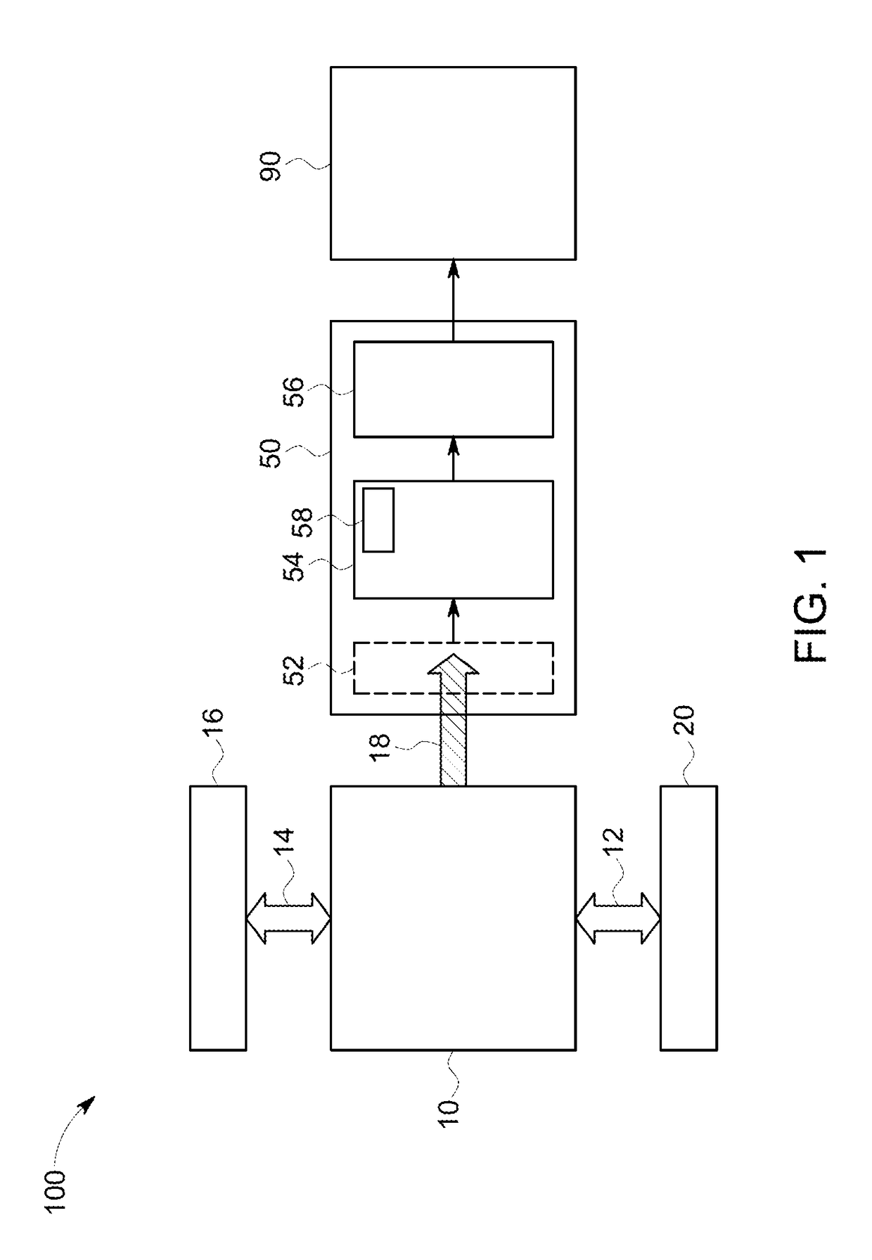
[0026]FIG. 1 shows an avionics display system 100 in accordance with an embodiment of the present innovation. The avionics display system 100 uses an improved graphics processing technique for displaying a scene in an aircraft cockpit. Additionally, it enables the use of standard components, that can be already standards certified, cheaper, simpler and / or lighter, such that reliability is improved and so that certification by various aviation authorities (FAA, CAA etc.) of the whole system may be made more likely.

[0027]The avionics display system 100 includes a central processing unit (CPU) 10. CPU 10 is connected to avionics 20 through avionics bus 12. Data relating to flight instruments is transmitted to the CPU 10 through the avionics bus 12, is then processed by the CPU 10 and subsequently used for displaying flight data on a display 90. In certain embodiments, CPU 10 may be part of a redundant system, for example, including a plurality of similar CPU's that process substantiall...


PUM


Abstract

The avionics display system is for displaying a scene in an aircraft cockpit. The avionics display system includes a central processing unit CPU, a graphics processing unit GPU operably coupled to the CPU, and a display. The GPU comprises at least one vertex shader, and the CPU is configured to provide vertex data representing at least one graphics primitive to the at least one vertex shader and to call the at least one vertex shader in order to render the at least one graphics primitive, representing at least a part of the scene, into a frame buffer. The display is operably coupled to the frame buffer and displays the scene. The system architecture of the avionics display system simplifies the coding process for the developer and also speeds up image processing in comparison to conventional systems.

Description

FIELD[0001]Embodiments of the present innovation relate generally to an avionics display system for use in various types of aircraft.BACKGROUND[0002]Over the last few decades the use of glass cockpits for aircraft, in which traditional analogue instrument displays have been replaced by on-screen electronic instrument displays, has become increasingly common even in light aircraft. Indeed, since the late 1980's certified electronic flight instrument systems (EFIS's) including such electronic instrument displays have become standard equipment on most Boeing® and Airbus® airliners.[0003]Whilst recent advances in computing power, and reductions in the cost of display screens and navigational sensors (such as global positioning satellite (GPS) systems, attitude and heading reference systems etc.), have brought EFIS's to a wider market, they generally still use manufacturer-specific proprietary technology to provide the complex high-resolution graphics needed to provide the specific essen...

Claims


Application Information

Patent Timeline
Patent Type & Authority Patents(United States)
IPC IPC(8): G06T15/50G06T15/80G06T1/20G06T1/60
CPCG06T15/80G06T1/60G06T1/20G06T11/20G06T15/005G06T2200/12G06T2210/22G06T2210/52
Inventor CATTON, LEWIS WILLIAM
Owner GE AVIATION SYST LTD
Why Eureka
Try Eureka