Transcatheter heart valve replacement systems, heart valve prostheses, and methods for percutaneous heart valve replacement

a heart valve and transcatheter technology, applied in the field of transcatheter heart valve replacement systems, can solve the problems of heart failure, heart pain, fainting, thickened heart that loses elasticity and efficiency, and heart failure to be less efficien

Active Publication Date: 2018-04-03
MEDTRONIC INC
View PDF12 Cites 36 Cited by
  • Summary
  • Abstract
  • Description
  • Claims
  • Application Information

AI Technical Summary

Problems solved by technology

Aortic stenosis, for example, can lead to chest pain, fainting, and heart failure.
Valvular insufficiency or regurgitation occurs when the valve does not close completely, allowing blood to flow backwards, thereby causing the heart to be less efficient.
A diseased or damaged valve, which can be congenital, age-related, drug-induced, or in some instances, caused by infection, can result in an enlarged, thickened heart that loses elasticity and efficiency.
Such symptoms can often be severe enough to be debilitating and / or life threatening.
While these prosthetic valves offer minimally invasive methods for heart valve repair and / or replacement, challenges remain to provide prosthetic valves that prevent leakage between the implanted prosthetic valve and the surrounding tissue (paravalvular leakage) and for preventing movement and / or migration of the prosthetic valve that could occur during the cardiac cycle.
For example, the repair or replacement of the aortic valve can present numerous challenges due to differing anatomies and etiologies presented by individual patients.
In a particular example, stenosis of the aortic valve can deform the valvular area which can result in paravalvular leakage around an implanted replacement valve.

Method used


Image

  • Transcatheter heart valve replacement systems, heart valve prostheses, and methods for percutaneous heart valve replacement
  • Transcatheter heart valve replacement systems, heart valve prostheses, and methods for percutaneous heart valve replacement
  • Transcatheter heart valve replacement systems, heart valve prostheses, and methods for percutaneous heart valve replacement

Examples


Embodiment Construction

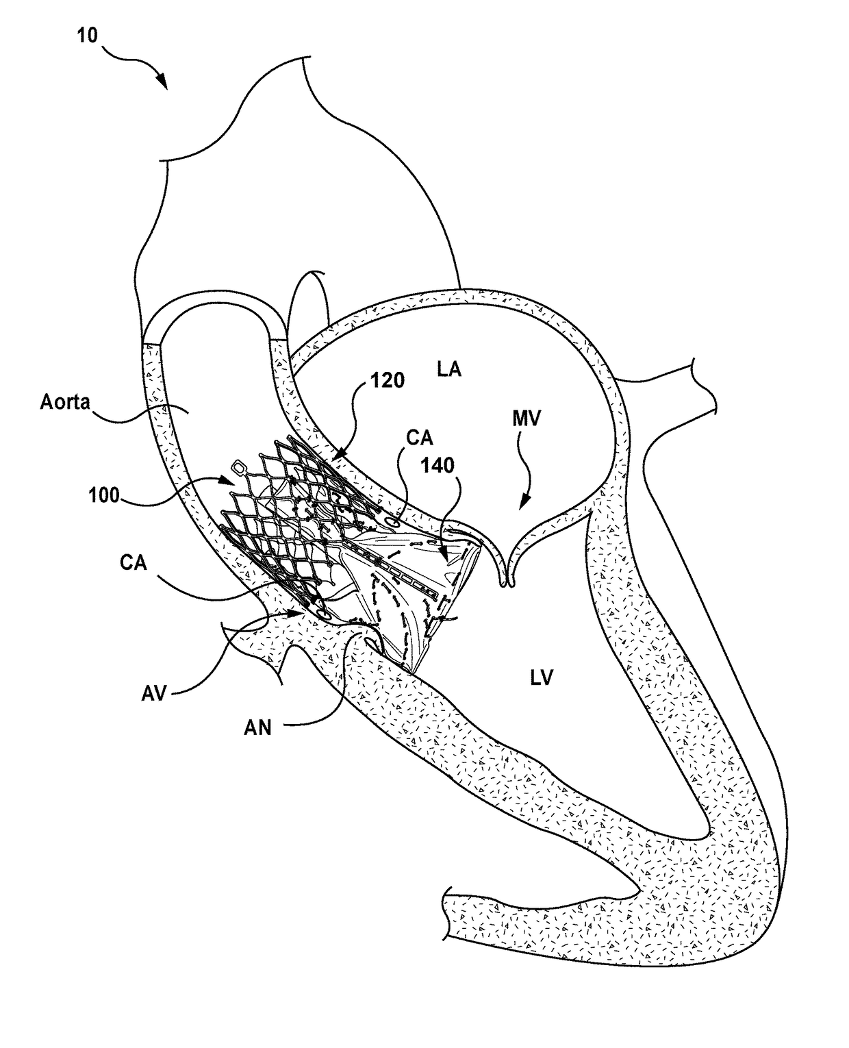
[0026]Specific embodiments of the present technology are now described with reference to the figures, wherein like reference numbers indicate identical or functionally similar elements. The terms “distal” and “proximal” are used in the following description with respect to a position or direction relative to the treating clinician or with respect to a prosthetic heart valve device. For example, “distal” or “distally” are a position distant from or in a direction away from the clinician when referring to delivery procedures or along a vasculature. Likewise, “proximal” and “proximally” are a position near or in a direction toward the clinician. With respect to a prosthetic heart valve device, the terms “proximal” and “distal” can refer to the location of portions of the device with respect to the direction of blood flow. For example, proximal can refer to an upstream position or a position of blood inflow, and distal can refer to a downstream position or a position of blood outflow.

[0...


PUM


Abstract

A transcatheter heart valve prosthesis configured in accordance herewith includes an expandable frame having a plurality of commissure posts extending therefrom, a radially expandable inflow member attached to the plurality of commissure posts, and a locking mechanism operably coupled to a wire. The wire is at least partially slideably disposed within a channel formed in a wall of the inflow member and the locking mechanism is configured to permit the wire to be advanced within the channel to thereby transition the inflow member into a deployed configuration that at least partially engages tissue at the native heart valve.

Description

FIELD OF THE INVENTION[0001]The present technology relates generally to heart valve prostheses, transcatheter heart valve replacement systems and associated methods. In particular, several embodiments are directed to transcatheter heart valve systems and devices for percutaneous replacement of heart valves, such as an aortic valve.BACKGROUND OF THE INVENTION[0002]The human heart is a four chambered, muscular organ that provides blood circulation through the body during a cardiac cycle. The four main chambers include the right atria and right ventricle which supplies the pulmonary circulation, and the left atria and left ventricle which supplies oxygenated blood received from the lungs to the remaining body. To insure that blood flows in one direction through the heart, atrioventricular valves (tricuspid and mitral valves) are present between the junctions of the atria and the ventricles, and semi-lunar valves (pulmonary valve and aortic valve) govern the exits of the ventricles lead...

Claims


Application Information

Patent Timeline
Patent Type & Authority Patents(United States)
IPC IPC(8): A61F2/24
CPCA61F2/2418A61F2/243A61F2/2409A61F2/2436A61F2/2427A61F2250/001A61F2220/0008A61F2250/0004A61F2250/0069A61F2/9517
Inventor ROTHSTEIN, PAULSANDSTROM, JEFFREY
Owner MEDTRONIC INC
Why Eureka
Try Eureka