
Autoinjector

a technology of injection device and injection needle, which is applied in the direction of injection needle, intravenous device, automatic syringe, etc., can solve the problems of undesirable automatic retraction, delay and expense,

Active Publication Date: 2018-05-01
EVERGREEN ENTERPRISES OF VIRGINIA +1
View PDF31 Cites 0 Cited by
  • Summary
  • Abstract
  • Description
  • Claims
  • Application Information

AI Technical Summary

Benefits of technology

The present invention provides an autoinjector with controlled needle retraction. The user can easily move the outer housing to retract the needle, without feeling or seeing any rotating components. The operation is performed by a single component (the inner housing), making the device reliable and efficient. The needle is blocked in a second position to prevent accidental needle stics. The tab and feet mechanism prevents the syringe support from moving forward when the needle is in the second position.

Problems solved by technology

Any modification to the standard syringe may require further trials and approval, adding delay and expense.
It is known that, in some cases, automatic retraction is undesirable as excessively quick retraction of the needle after delivery may cause the medicament to escape from the puncture hole created by the needle in the tissue.
This is especially true if the liquid has not dispersed into the tissue and is in a “pressurised bolus” at the point of delivery which is a known problem when injecting adrenaline, for example.

Method used


Image

  • Autoinjector
  • Autoinjector
  • Autoinjector

Examples


Embodiment Construction

[0045]Throughout the following description, reference to a “forward” direction means the direction which is towards the patient when the injection device is in use. The “forward” end of the injection device is the end nearest the patient's skin when the device is in use. Similarly, reference to a “rearward” direction means the direction which is away from the patient and the “rearward” end of the device is the end furthest from the patient's skin when the injection device is in use.

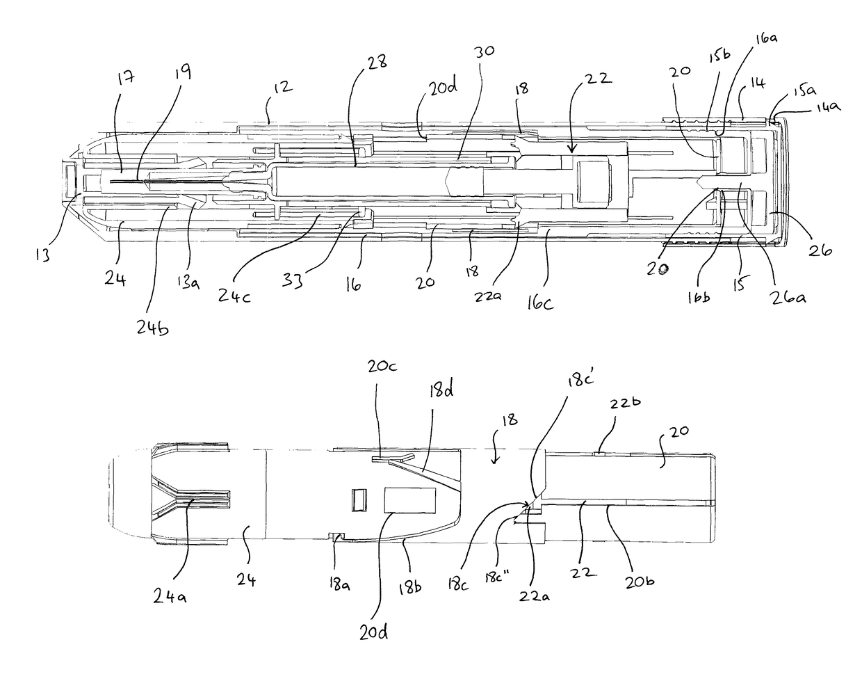
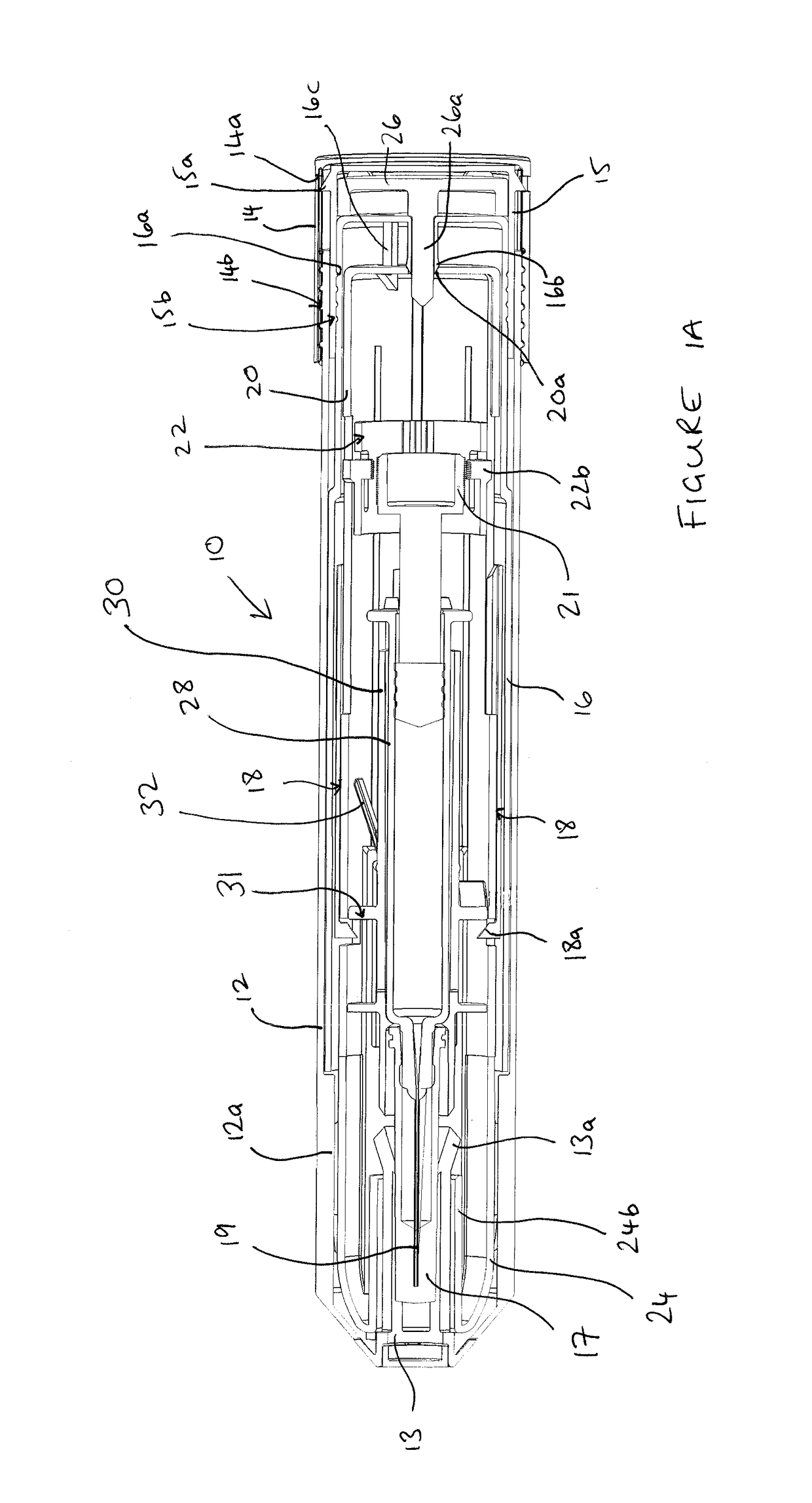
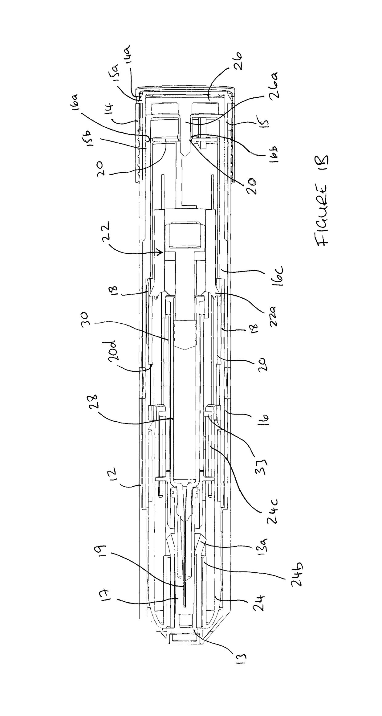
[0046]An exemplary embodiment 10 of an autoinjector according to the present invention is shown FIGS. 1A and 1B. The autoinjector 10 contains a syringe 28 having a needle 19 and may be actuated by a user to automatically deliver a dose of medicament to them self or another patient.

[0047]The autoinjector 10 is initially stored in an outer packaging 12 and a rear screw cap 14 screwed thereto via a screw thread 14b. The rear screw cap 14 surrounds a rear end cap 15 and has radial apertures 14a that radial pr...


PUM


Abstract

An autoinjector including: a housing, in which can be mounted a syringe (28) having a plunger, a barrel and needle (19) at one end thereof through which medicament can be delivered to an injection site,—a syringe support means (30) capable of causing said syringe to move along an axial path with respect to said housing; biasing means capable of biasing said syringe support means so that said needle is normally inside said housing; and engagement means (180) selectively moveable by a user from a first position in which rearward movement of the syringe along said axial path is substantially prevented when said syringe is in an extended position where at least part of said needle is out of the housing, to a second position in which rearward movement of the syringe along said axial path relative to said housing is possible and said biasing means causes said needle to retract inside said housing; wherein said housing includes an outer housing (16) and said autoinjector further comprises a sleeve (18) intermediate the syringe support means and said outer housing that is capable of moving the engagement means between said first and second positions by rotating said sleeve about a longitudinal axis of said autoinjector between a first rotational position and a second rotational position; and wherein the sleeve is moveable between said first and second rotational positions by moving said outer housing with respect to the sleeve in a substantially axial direction.

Description

CROSS-REFERENCE TO RELATED APPLICATIONS[0001]This application is a national stage application under 35 U.S.C. § 371 of International Application No. PCT / GB2010 / 051257, titled IMPROVED AUTOINJECTOR, filed Jul. 30, 2010, which claims priority to Great Britain Patent Application No. 0913385.1, filed Jul. 31, 2009, both of which are hereby incorporated by reference in their entireties.[0002]This invention relates to the field of autoinjectors for delivering a dose of medicament and, in particular, the invention relates to autoinjectors having a mechanism to control the retraction of the needle from an injection site.BACKGROUND[0003]An autoinjector is an automatic injection device designed to facilitate automated delivery of a dose of medicament to a patient through a hypodermic needle, the injection usually being administered by the patient themselves. An autoinjector works, for example, by delivering an injection automatically upon actuation by the patient pressing a button, moving a l...

Claims


Application Information

Patent Timeline
Patent Type & Authority Patents(United States)
IPC IPC(8): A61M5/20A61M5/00A61M5/32A61M5/315
CPCA61M5/2033A61M5/002A61M5/31571A61M5/31591A61M5/3257A61M2005/2073A61M5/31555A61M5/3204A61M5/3271A61M2005/206A61M2005/2013A61M5/3158
Inventor CLEATHERO, IAN
Owner EVERGREEN ENTERPRISES OF VIRGINIA
Learn More