Headlight device for motorcycle

a headlight device and motorcycle technology, applied in the direction of bicycle equipment, lighting and heating equipment, optical signals, etc., can solve the problem of difficulty in securing the arrangement space of the power supply circuit uni

Active Publication Date: 2018-05-08
KAWASAKI MOTORS LTD
View PDF25 Cites 2 Cited by
  • Summary
  • Abstract
  • Description
  • Claims
  • Application Information

AI Technical Summary

Benefits of technology

[0008]In view of the aforementioned problem, an object of the present invention is to provide a headlight device for a motorcycle, in which LEDs and a power supply circuit unit can be accommodated in a front fairing in a compact manner while downsizing the front fairing.
[0010]With this configuration, since the LED light source is used, the lamp unit can be downsized. When the downsized lamp unit is located at the lowermost position in the front fairing, the lamp unit can be easily accommodated in the front fairing even when the front fairing is downsized. The front fairing generally has a tapered shape having an upper portion of a small length in the front-rear direction or the longitudinal direction, and a lower portion of a large length in the longitudinal direction. Therefore, it is preferable for the downsized front fairing that the lamp unit is located at the lower position in the front fairing where a sufficient space is secured. At this time, since the power supply circuit unit is accommodated in the recess provided above the lamp unit, the lamp unit can be located at the lower position in the front fairing without being obstructed by the power supply circuit unit. Thus, the lamp unit and the power supply circuit unit can be accommodated in the front fairing in a compact manner while downsizing the front fairing.
[0012]When the elastic body is provided, it is preferable that the recess is provided in the upper portion of the lamp unit, and the power supply circuit unit is accommodated in a box formed of the elastic body and opened upward, and the box is pressed against an inner surface of the recess. With this configuration, since the power supply circuit unit is incorporated in the lamp unit by only accommodating the box in the recess, the assembly is facilitated. Further, since the box is pressed against the inner surface of the recess, the relative position of the box to the lamp unit is made stable. Thereby, for example, the box and a lamp bracket can be connected not by fastening but by a simple insertion-type locking structure. Further, since the box is formed of an elastic body, vibration transmitted from the lamp bracket during traveling of the motorcycle is also absorbed.
[0013]In the present invention, it is preferable that the power supply circuit unit and the lamp unit are supported by a lamp bracket, and the lamp bracket is mounted to a top bridge which supports a front fork. In this case, it is preferable that the lamp bracket is mounted to the top bridge through a mounting bracket. With this configuration, since the lamp bracket supports both the lamp unit and the power supply circuit unit, the number of components and the number of assembling steps are reduced. Further, an assembly is configured by connecting the lamp bracket and the mounting bracket to the headlight device and the front fairing, and the assembly is mounted to the top bridge, whereby the headlight device and the front fairing are assembled to the vehicle body. Therefore, assemblability of the headlight device and the front fairing is improved.
[0014]When the mounting bracket is provided, it is preferable that the mounting bracket is provided with a first holding member which allows cables to pass therethrough and holds the cables. In this case, it is further preferable that the lamp bracket is provided with a second holding member which holds the cables in cooperation with the first holding member. With this configuration, since the mounting bracket and the lamp bracket are provided with the first and second holding members, respectively, the mounting bracket and the lamp bracket can also be used for holding the cables. Further, when the above-described assembly is configured, the cables are held by the first and second holding members, whereby assemblability is improved.

Problems solved by technology

Since the shape of the front fairing is determined in view of its function and appearance, it is difficult to secure an arrangement space for the power supply circuit unit if the front fairing is downsized.

Method used


Image

  • Headlight device for motorcycle
  • Headlight device for motorcycle
  • Headlight device for motorcycle

Examples


Embodiment Construction

[0028]Hereinafter, preferred embodiments of the present invention will be described with reference to the drawings. In the description herein, “left side” and “right side” refer to the left side and right side, respectively, as viewed by a rider riding a vehicle.

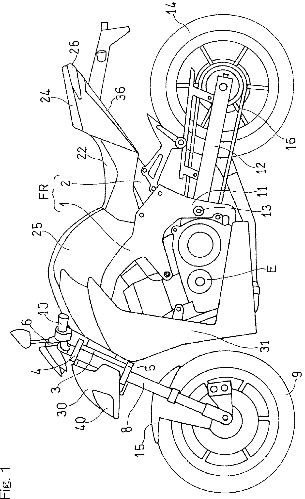
[0029]FIG. 1 shows a motorcycle to which the present invention is applied. A motorcycle body frame structure FR of the motorcycle includes a main frame 1, forming a front half thereof, and a rear frame 2 forming a rear half thereof. The rear frame 2 is connected to a rear portion of the main frame 1. A head pipe 3 is mounted to a front end of the main frame 1, and a steering shaft (not shown) is rotatably inserted into the head pipe 3. A top bridge 4 and a bottom bridge 5 are mounted to the steering shaft, and a front fork 8 is supported by the top bridge 4 and the bottom bridge 5. A front wheel 9 is supported by a lower end portion of the front fork 8, and a front fender 15 is mounted above the front wheel 9. A handlebar 10...


PUM


Abstract

A headlight device (40) for a motorcycle is accommodated in a front fairing (30). The headlight device (40) includes lamp units (42) using LEDs as light sources (46a, 48a), and a power supply circuit unit (44) which controls power from a power supply and supplies the power to the light sources (46a, 48a). The power supply circuit unit (44) is accommodated in a recess (56) provided in an upper portion of the lamp units (42).

Description

CROSS REFERENCE TO THE RELATED APPLICATION[0001]This application is a continuation application, under 35 U.S.C § 111(a) of international application No. PCT / JP2013 / 078838, filed Oct. 24, 2013, which claims priority to Japanese patent application No. 2012-273252, filed Dec. 14, 2012, the entire disclosure of which is herein incorporated by reference as a part of this application.BACKGROUND OF THE INVENTION[0002]Field of the Invention[0003]The present invention relates to headlight devices for motorcycles, using LEDs (light emitting diodes) as light sources. In particular, the present invention relates to a headlight device mounted to a front fairing of a motorcycle.[0004]Description of Related Art[0005]In recent years, LEDs have been increasingly adopted as light sources of headlight devices for motorcycles (for example, Patent Document 1). Since a headlight device using LEDs is smaller in size as compared to a conventional headlight device using bulbs, downsizing of a front fairing ...

Claims


Application Information

Patent Timeline
Patent Type & Authority Patents(United States)
IPC IPC(8): B62J6/02B60Q1/04B62J6/18B60Q1/00F21V23/00B62J11/19
CPCB60Q1/0483B60Q1/0094B62J6/18B62J6/02F21V23/008B60Q1/04B62J6/026B62J11/19B62J6/027
Inventor TAKAYA, SATOSHI
Owner KAWASAKI MOTORS LTD
Why Eureka
Try Eureka