Centrifugal blower

a centrifugal fan and centrifugal fan technology, which is applied in the direction of liquid fuel engines, electric apparatus casings/cabinets/drawers, instruments, etc., can solve the problems of violating compact size requirements, increasing the size of electronic products, and occupying more space for centrifugal fans in electronic products, etc., to achieve the effect of increasing the size of centrifugal fans and receiving precise data

Inactive Publication Date: 2012-02-07
HON HAI PRECISION IND CO LTD
View PDF13 Cites 4 Cited by
  • Summary
  • Abstract
  • Description
  • Claims
  • Application Information

AI Technical Summary

Benefits of technology

[0006]The present invention relates, in one aspect, to a centrifugal blower. The centrifugal blower includes a casing and a rotor rotatably disposed in the casing. The casing includes a base plate, a sidewall extending from the base plat; and a cover covering the sidewall. The sidewall is a multilayer structure and includes a first section and a second section. A distance between a central axis of the rotor and an inner surface of the second section is greater than that between the central axis of the rotor and an inner surface of the first section. Accordingly, the centrifugal blower can be compactly received in a portable electronic device with the first section located below a printed circuit board of the electronic device and the second section having a portion sitting on the printed circuit board. Thus, the size of the centrifugal fan can be increased while being compactly accommodated in the portable electronic device.

Problems solved by technology

That is, a sidewall of a casing of the centrifugal blower or a diameter of a rotor of the centrifugal blower is increased, which causes the centrifugal blowers to occupy more space in electronic products.
The sizes of the electronic products are accordingly increased, which violates the compact size requirements for the electronic products.
Thus, there is a need to provide centrifugal blowers having higher heat removal capacities, but with the sizes of the electronic products accommodating the centrifugal blowers therein not increasing.

Method used


Image

  • Centrifugal blower
  • Centrifugal blower
  • Centrifugal blower

Examples


Embodiment Construction

[0014]Reference will now be made to the drawing figures to describe the first embodiment in detail.

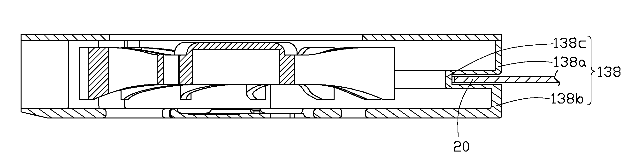
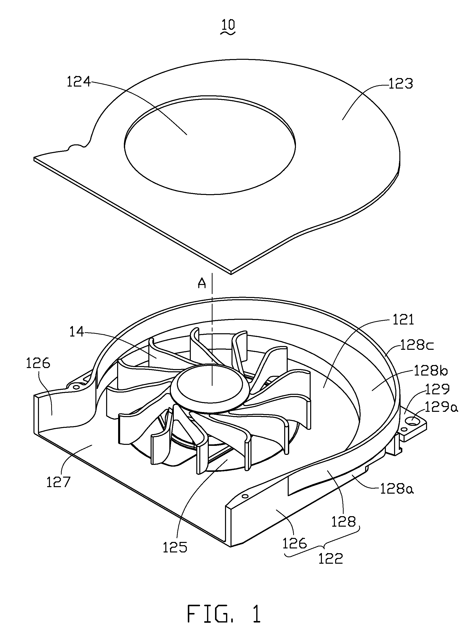
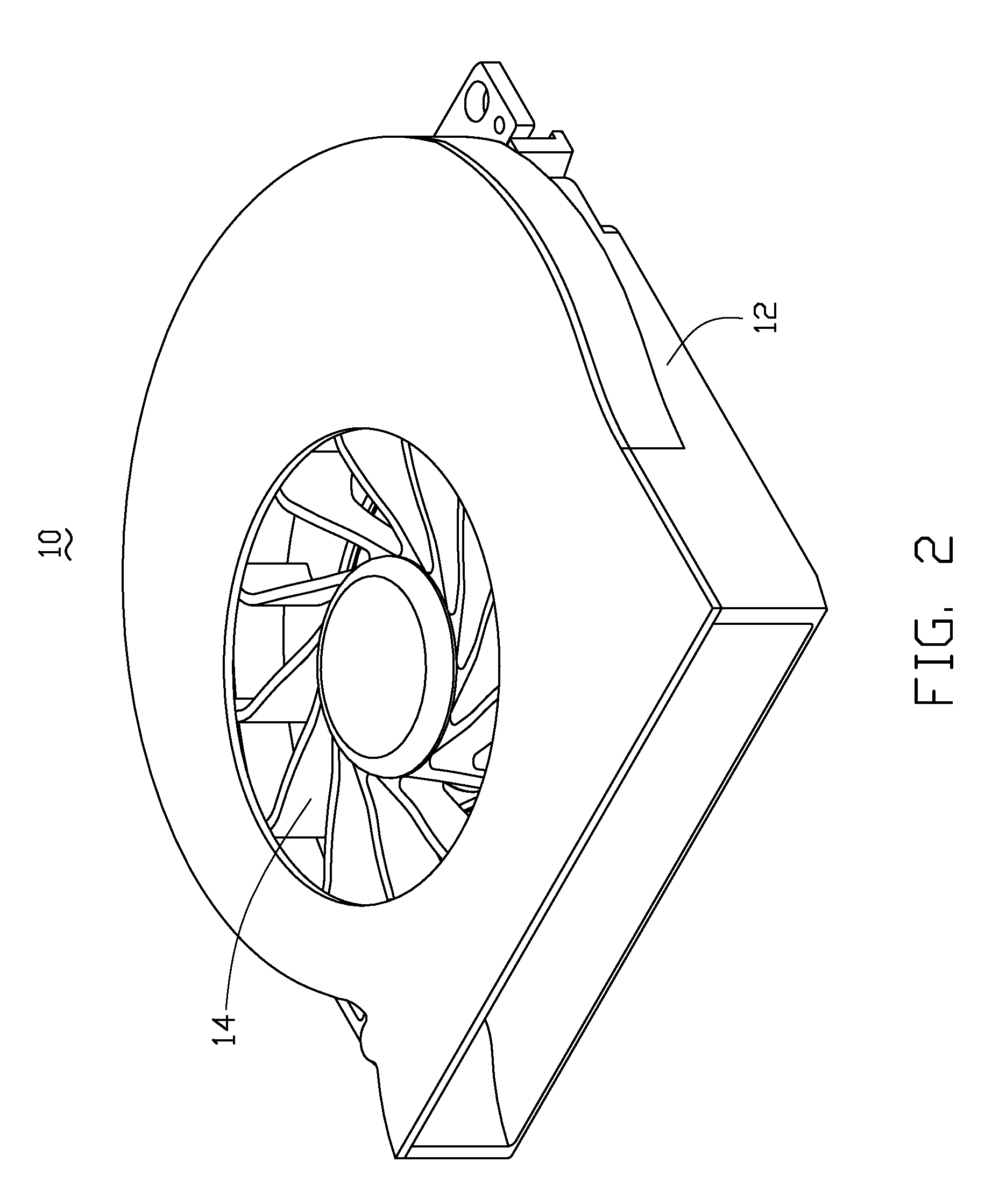
[0015]Referring to FIGS. 1 to 5, a centrifugal blower 10 in accordance with a preferred embodiment of the present invention is shown. The centrifugal blower 10 is mounted to a motherboard 20 of an electronic product such as a laptop computer, and includes a casing 12 (shown in FIG. 2) and a rotor 14 disposed in the casing 12.

[0016]The casing 12 includes a planar base plate 121, and a substantially U-shaped sidewall 122 extending upwardly from a periphery of the base plate 121 and a top cover 123 covering the sidewall 122. The base plate 121 and the top cover 123 respectively define an air inlet 124, 125 therein. The rotor 14 is disposed in a space formed between the base plate 121, the sidewall 122 and the top cover 123. The sidewall 122 includes two opposite walls 126 which define an air outlet 127 therebetween, and a volute shell 128 which is located between and connects with the opp...


PUM


Abstract

A centrifugal blower (10) includes a casing (12) and a rotor (14) rotatable disposed in the casing. The casing includes a base plate (121), a sidewall (122) extending from the base plate and a cover (123) covering the sidewall. The sidewall is a multilayer structure and includes a first section (128a) and a second section (128c). A distance between a central axis (A) of the rotor and an inner surface of the second section is greater than that between the central axis of the rotor and an inner surface of the first section. The first section is located below a mother board (20) and the second section sits on a top surface of the motherboard when the centrifugal blower is mounted to the mother board.

Description

BACKGROUND OF THE INVENTION[0001]1. Field of the Invention[0002]The present invention relates generally to centrifugal blowers, and more particularly to a centrifugal blower which can provide a large amount of airflow while be compactly received in a portable electronic device.[0003]2. Related Art[0004]It is well known that heat is generated during operations of a variety of electronic components, such as integrated circuit chips. To ensure normal and safe operations, cooling devices such as centrifugal blowers are often employed to dissipate the generated heat away from these electronic components.[0005]As progress continues to be made in the electronics area, more components are accommodated on the same real estate and generate more heat. The centrifugal blowers used to cool these electronic components are accordingly made as large as possible in order to possess higher heat removal capacities. That is, a sidewall of a casing of the centrifugal blower or a diameter of a rotor of t...

Claims


Application Information

Patent Timeline
Patent Type & Authority Patents(United States)
IPC IPC(8): F04D29/58
CPCF04D25/0613F04D29/582F04D29/601G06F1/203
Inventor HWANG, CHING-BAIHUNG, JUI-WEN
Owner HON HAI PRECISION IND CO LTD
Why Eureka
Try Eureka