
Particulate matter detection device

a detection device and a technology for particles, applied in the direction of machines/engines, electrical control, instruments, etc., can solve the problems of ineffective electrical charging of particulates and high cost of devices, and achieve the effects of accurate detection, improved measurement sensitivity of electric characteristics, and high accuracy in measuring

Active Publication Date: 2010-01-07
NGK INSULATORS LTD +1
View PDF26 Cites 37 Cited by
  • Summary
  • Abstract
  • Description
  • Claims
  • Application Information

AI Technical Summary

Benefits of technology

[0007]However, in a method described in Patent Document 1, a particulate matter is electrically charged with a weak ion current, and a large-scaled detection circuit for detecting such a weak ion current is required, whereby a device becomes expensive. In addition, when the flow rate of an exhaust gas is large, the particulate matter cannot effectively electrically be charged, and a measured value becomes smaller than the amount of the particulate matter actually included in the exhaust gas. Therefore, there is a room for the improvement of accuracy.
[0008]The present invention has been developed in view of such a situation, and an object thereof is to provide a particulate matter detection device which can easily detect the particulate matter and which is inexpensive and which has a high measurement accuracy. As a result of repeated investigations, it has been found that the following means can solve this problem.

Problems solved by technology

However, in a method described in Patent Document 1, a particulate matter is electrically charged with a weak ion current, and a large-scaled detection circuit for detecting such a weak ion current is required, whereby a device becomes expensive.
In addition, when the flow rate of an exhaust gas is large, the particulate matter cannot effectively electrically be charged, and a measured value becomes smaller than the amount of the particulate matter actually included in the exhaust gas.

Method used


Image

  • Particulate matter detection device
  • Particulate matter detection device
  • Particulate matter detection device

Examples


Embodiment Construction

[0108]Hereinafter, embodiments of the present invention will be described appropriately with reference to the drawings, but the present invention is not limited to these embodiments when interpreted. The present invention can variously be altered, modified, improved or replaced based on the knowledge of any person skilled in the art without departing from the scope of the present invention. For example, the drawings show preferable embodiments of the present invention, but the present invention is not limited to configurations or information shown in the drawings. To implement or verify the present invention, means similar or equivalent to means described in the present specification is applicable, but preferable means is the following means.

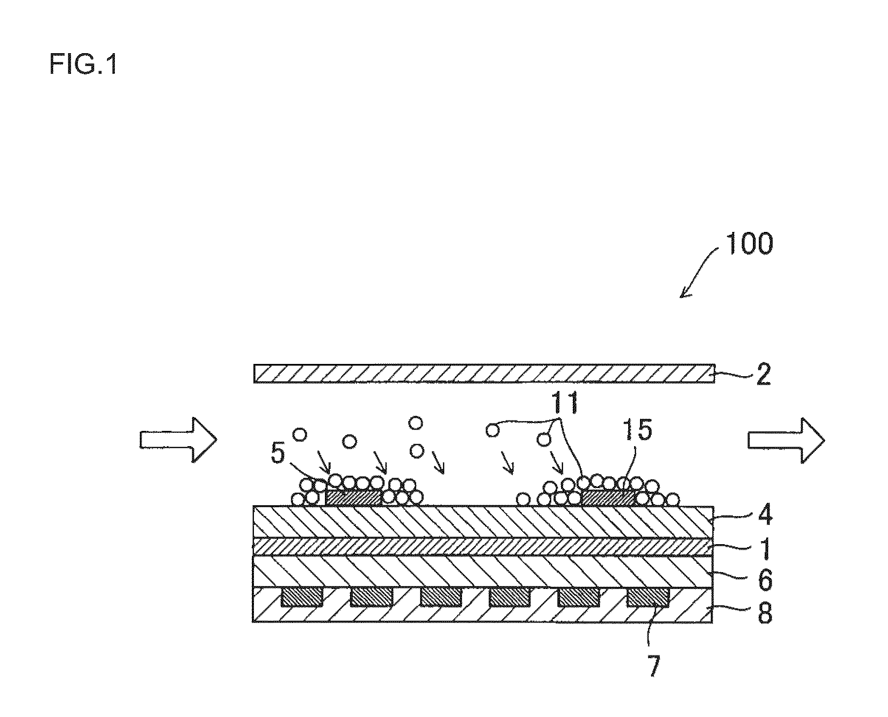
[0109][(1) First Particulate Matter Detection Device] First, a constitution, function, operation and the like of a first particulate matter detection device according to the present invention will mainly be described.

[0110]FIGS. 1 and 7 are diag...


PUM

PropertyMeasurementUnit
distanceaaaaaaaaaa
distanceaaaaaaaaaa
distanceaaaaaaaaaa

Abstract

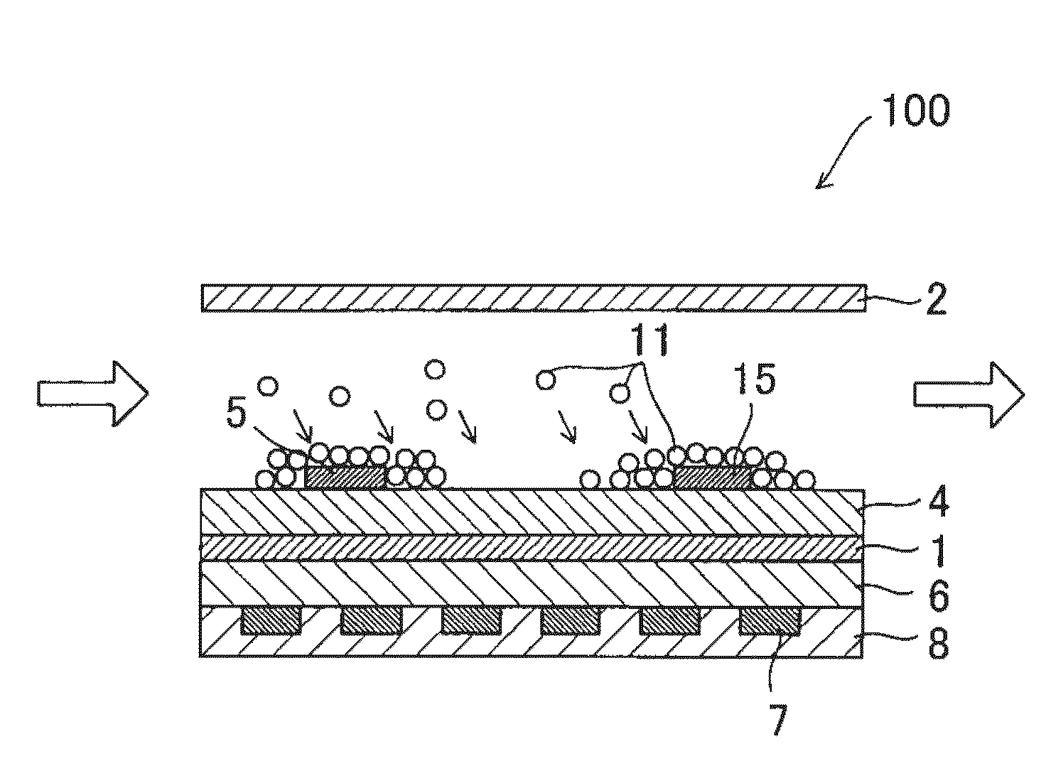
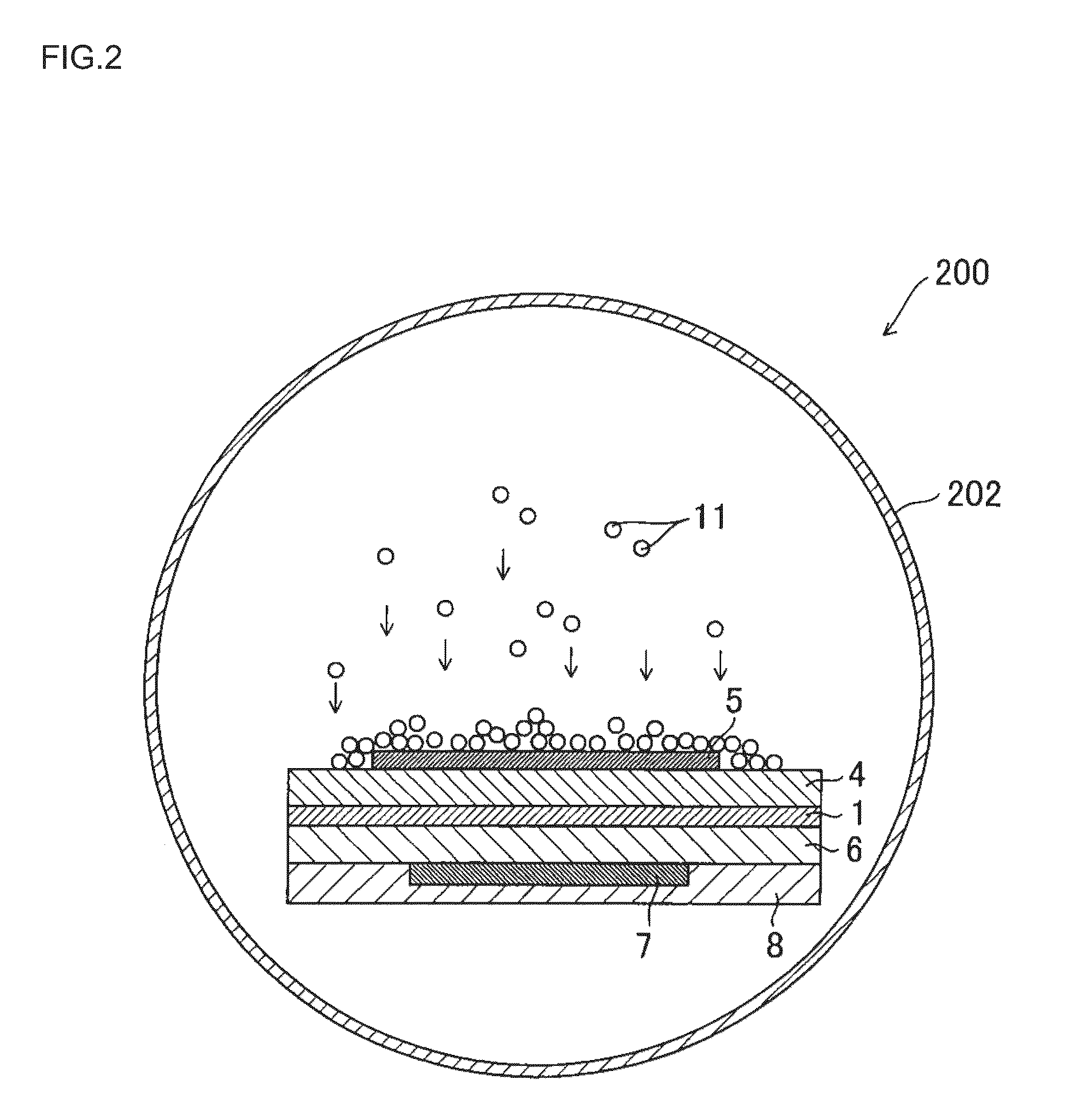
A particulate matter detection device 100 includes a first electrode 1 whose one surface is covered with an inter-electrode dielectric material 4; a second electrode 2 disposed on the side of the one surface of the first electrode 1, to perform the discharge of electricity by a voltage applied between the first electrode 1 and the second electrode; and a pair of measurement electrodes 5, 15 disposed on the surface of the inter-electrode dielectric material 4 so as to face each other; characteristic measurement means 3 for measuring electric characteristics between the pair of measurement electrodes 5 and 15; and particulate matter amount calculation means 13 for obtaining the amount of the particulate matter 11 collected by the surface of the inter-electrode dielectric material 4, based on the change amount of the electric characteristics.

Description

BACKGROUND OF THE INVENTION[0001]1. Field of the Invention[0002]The present invention relates to a device which detects a particulate matter included in an exhaust gas from a diesel engine or the like.[0003]2. Description of the Related Art[0004]An exhaust gas from a diesel engine or the like includes a particulate matter (PM) detected as three components, that is, an organic solvent soluble component, soot and sulfate, which causes air pollution. In particular, when a defect occurs in a particulate matter generation source such as the diesel engine, the particulate matter in the exhaust gas discharged to the atmosphere increases, and noticeably adversely affects the environment. For the prevention of this problem, it is essential to detect the particulate matter in the exhaust gas and recognize the defect of the diesel engine or the like.[0005]Moreover, in recent years, to prevent environmental pollution and improve the environment, a diesel particulate filter (DPF) for the treatme...

Claims


Application Information

Patent Timeline
Patent Type & Authority Applications(United States)
IPC IPC(8): G01N27/16
CPCF01N2560/05G01N15/0656F02D41/1466
Inventor KONDO, ATSUOSAKUMA, TAKESHIEGAMI, TAKASHIOKAYAMA, TATSUYAMIKI, MASANOBUIWAMA, KEIZO
Owner NGK INSULATORS LTD
Learn More