Effective-inductance-change based magnetic particle sensing

Active Publication Date: 2009-10-29
CALIFORNIA INST OF TECH
View PDF48 Cites 41 Cited by
  • Summary
  • Abstract
  • Description
  • Claims
  • Application Information

AI Technical Summary

Benefits of technology

[0039]In yet another embodiment, the step of measuring an parameter includes measuring an parameter of said sensor

Problems solved by technology

While the magnetic behavior of magnetic micro/nano beads can be detected without using costly imaging systems, sensing magnetic micro/nano particles remains a challenging task.
However, sensing methods such as those based on SQUIDs or GMR arrays typically cannot be fabricated with standard integrated processes as CMOS.
Also, both SQUID and GMR array generally require relatively costly postprocessing steps.
Moreover, GMR techniques need externally generated biasing magnetic fields.
Such biasing magnetic fields can be provided using either permanent or electro-magnets, which leads to extra power-consumption, large form-factor and high cost.
Moreover, the biasing

Method used


Image

  • Effective-inductance-change based magnetic particle sensing
  • Effective-inductance-change based magnetic particle sensing
  • Effective-inductance-change based magnetic particle sensing

Examples


implementation example

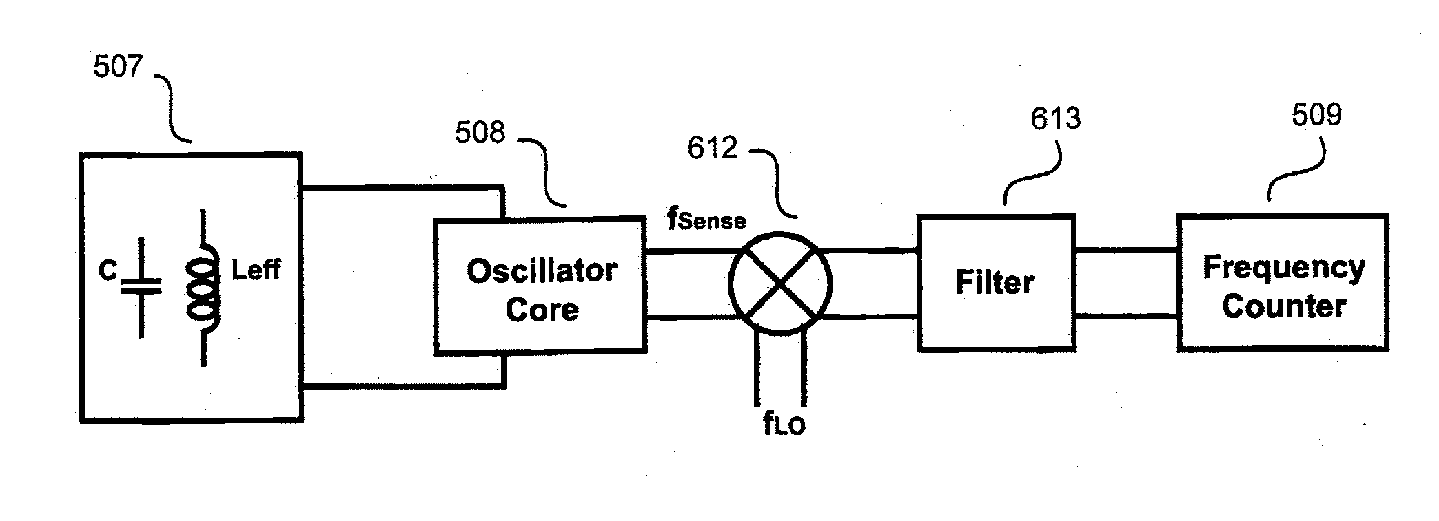
[0112]Two experiments using laboratory test setups of two embodiments of a magnetic particle sensor based on the sensing mechanisms as described above are now described. An LC resonator (as described in section III above) was used as the sensor core. A low noise Colpitts oscillator was built based on a resonator, and the sensor was powered at 4.5V by 3 AA batteries. Thin-film technology was adopted to fabricate both the circuit board and the inductors. FIG. 12 shows an illustration of the sensor circuitry. FIG. 13 shows a schematic diagram of the magnetic particle sensor based on Colpitts LC oscillator. Inductor Ls is used as the sensing inductor. Together with C1 and C2, inductor Ls forms the resonator of block 507 in FIG. 5. Transistor T1 forms the oscillator core as block 508 in FIG. 5. R1, R2, Re, Lc are present for biasing purposes, while C3 and C4 are used for coupling and bypass purposes. An off-the shelf model 53150A HP frequency counter was used for frequency counting as bl...

experiment 1

[0113]Experiment 1 demonstrated magnetic particle sensing without a micro-fluidic channel. The objective of this experiment was to test the functionality of the sensor in an open environment condition (without a fluidic channel). FIG. 14 shows a flowchart of the experimental procedures used to perform experiment 1. The surface temperature of the chip rises during operation of the sensor. This thermal effect, together with the open environment, induces fast vaporization of the DI water in the magnetic particle solution. Note that the baseline measurement (frequency counting on f2) and the target measurement (frequency counting on f1) together with its sample delivery can be interchanged in time. Therefore, the recorded frequency f1 and f2 corresponds to an oscillation frequency of dried beads in the inductors and an oscillation frequency with a dried inductor surface, after achieving the thermal steady-state. The sensitivity can be further defined by Eq. 4:

Δff=f2-f1f2(Eq.4)

[0114]FIG....

experiment 2

[0115]Experiment 2 demonstrated magnetic particle sensing using a micro-fluidic channel. The objective of this experiment was to test the functionality of the bio-sensor in an enclosed aqueous condition. A microfluidic channel together with pneumatic control valves were fabricated in a poly-dimethylsiloxane (PDMS) material. The microfluidic channel and pneumatic control valves were used to deliver magnetic particle samples to the sensor, as well as to form a sensing chamber. The sensing chamber substantially prevented vaporization of the DI water during detection. FIG. 18 shows a flowchart of the experimental procedures used to perform experiment 2. Note that the baseline measurement (frequency counting on f4) and the target measurement (frequency counting on f3) together with its sample delivery can be interchanged in time. As in experiment 1, the surface temperature of the chip rises during operation of the sensor.

[0116]During an operational mode of the sensor, the DI water was pr...


PUM


Abstract

The invention relates to an integrated measurement system to detect a quantity of magnetic particles in a sample. The measurement system includes a substrate. An electromagnetic (EM) structure disposed on the surface of the substrate is configured to receive a sample including the magnetic particles in proximity thereof. The integrated measurement system also includes an electrical current generator disposed on the surface of the substrate which is electro-magnetically coupled to the EM structure. The electrical current generator is configured to cause an electrical current to flow in the EM structure. The integrated measurement system also includes an effective inductance sensor disposed on the surface of the substrate which is configured to measure a selected one of an effective inductance and a change in effective inductance. The invention also relates to a method to determine the number of and/or the locations of the magnetic particles in a sample.

Description

CROSS-REFERENCE TO RELATED APPLICATIONS[0001]This application claims priority to and the benefit of co-pending U.S. provisional patent application Ser. No. 61 / 068,513, filed Mar. 7, 2008, which application is incorporated herein by reference in its entirety.STATEMENT REGARDING FEDERALLY FUNDED RESEARCH OR DEVELOPMENT[0002]The U.S. Government has certain rights in this invention pursuant to Grant No. N00014-04-C-0588 awarded by ONR—Space and Naval Warfare Systems Center.FIELD OF THE INVENTION[0003]The invention relates in general to bio-sensors and more particularly to micro / nano bead based cell / bio-molecule sensors.BACKGROUND OF THE INVENTION[0004]Non-optical methods for bioassay are of interest to the interdisciplinary fields of biology, applied physics, and microelectronics. Magnetic micro / nano beads have been studied for use in cell / bio-molecule sensing as one non-optical method. While the magnetic behavior of magnetic micro / nano beads can be detected without using costly imaging...

Claims


Application Information

Patent Timeline
IPC IPC(8): G01N27/00G01R33/00
CPCG01R33/1269
Inventor WANG, HUAHAJIMIRI, SEYED ALICHEN, YAN
Owner CALIFORNIA INST OF TECH
Why Eureka
Try Eureka