Light-permeable cover plate and mobile terminal

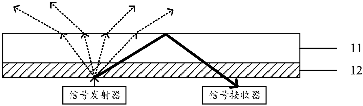
A light-transmitting cover and mobile terminal technology, which is applied in the field of communication, can solve the problems of large signal wave background noise, etc., and achieve the effect of reducing background noise and optimizing performance

Active Publication Date: 2018-12-21
VIVO MOBILE COMM CO LTD
View PDF12 Cites 1 Cited by
  • Summary
  • Abstract
  • Description
  • Claims
  • Application Information

AI Technical Summary

Problems solved by technology

[0004] Embodiments of the present application provide a light-transmitting cover plate and a mobile terminal to solve the problem in the prior art that the received signal wave has a large noise floor due to signal waves reflected and emitted by the cover plate

Method used


Image

  • Light-permeable cover plate and mobile terminal
  • Light-permeable cover plate and mobile terminal
  • Light-permeable cover plate and mobile terminal

Examples


Embodiment 1

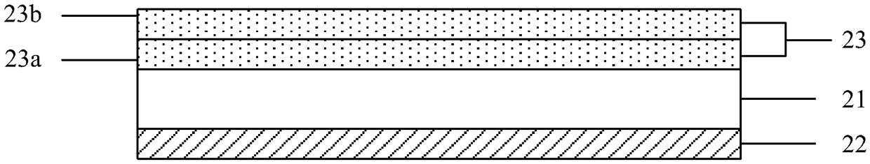
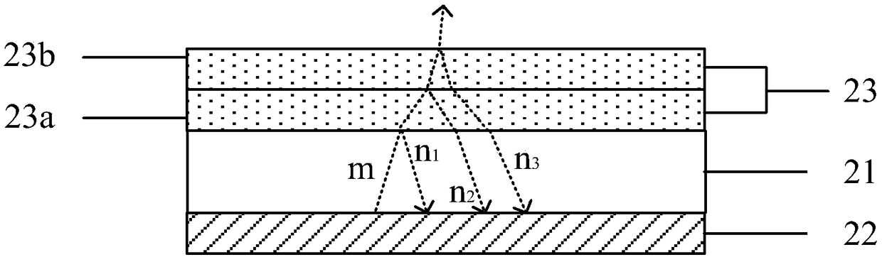
[0027] The embodiment of the present application provides a light-transmitting cover plate, figure 2 It is a schematic structural diagram of the light-transmitting cover, and the light-transmitting cover includes:

[0028] The light-transmitting cover body 21;

[0029] The light-transmitting film layer 23 is provided on the first side surface of the light-transmitting cover plate body 21, and includes at least two layers of light-transmitting films stacked in sequence;

[0030] The ink layer 22 is provided on the second side surface of the transparent cover body 21;

[0031] Wherein, the refractive index of the light-transmitting film adjacent to the light-transmitting cover body 21 is greater than the refractive index of the light-transmitting cover body 21, and the respective refractive indices of the at least two layers of light-transmitting films vary with each other. The distance between the transparent cover body 21 decreases; or, the refractive index of the transpare...

Embodiment 2

[0062] Based on the solutions described in the above embodiments, the present application also provides a light-transmitting cover plate to further illustrate the solution, as shown in Figure 5 As shown, the light-transmitting cover plate provided by this application includes:

[0063] A light-transmitting cover plate body 51, one side of the light-transmitting cover plate body 51 is coated with an ink layer 52;

[0064] At least two layers of light-transmitting films 53 located on the other side of the light-transmitting cover plate body 51;

[0065] Wherein, the refractive index of any transparent film 53 is related to the distance between the transparent film 53 and the transparent cover body 51 .

[0066] like Figure 5 As shown, in this example, the light-transmitting film on one surface of the light-transmitting cover body 51 has 4 layers in total, from close to the light-transmitting cover body 51 to away from the light-transmitting cover body 51 in sequence: the fir...

example 1

[0069] The refractive index of the first transparent film 53a is greater than the refractive index of the transparent cover body 51, the refractive index of the second transparent film 53b is smaller than that of the first transparent film 53a, and the refractive index of the third transparent film 53c is smaller than that of the first transparent film 53a. The refractive index of the second transparent film 53b and the refractive index of the fourth transparent film 53d are smaller than the refractive index of the third transparent film 53c.

[0070] Based on the structure shown in this example, when light radiates from the ink layer 52 to the outside, the light reflected at the contact surface between the first light-transmitting film 53a and the second light-transmitting film 53b can offset the contact between the light-transmitting cover body 51 and the first light-transmitting film. The light reflected at the contact surface of the transparent film 53a. Specifically, beca...


PUM


Abstract

The invention relates to the field of terminals, in particular to a light-permeable cover plate and a mobile terminal. The problem that received signal waves are large in bottom noise due to signal waves reflected and emitted by a cover plate in the prior art is solved. The cover plate comprises a light-permeable cover plate body, a light-permeable film layer and an ink layer, wherein the light-permeable film layer is arranged on the first side surface of the light-permeable cover plate body, and comprises at least two layers of light-permeable films sequentially overlapped, and the ink layeris arranged on the second side surface of the light-permeable cover plate body. By means of the light-permeable cover plate, when part of emitted signal waves are reflected, according to the half-waveloss principle, the reflected signal waves can counteract part of signal waves in the bottom noise, the bottom noise is reduced to a certain extent, and the performance of the received signal waves is optimized.

Description

technical field [0001] The present application relates to the technical field of communications, and in particular to a light-transmitting cover and a mobile terminal. Background technique [0002] In the existing electronic terminal field, in order to improve the appearance of the electronic terminal, ink is often coated on the surface of the signal transceiver, so that the position where the signal transceiver is located is consistent with the color of other areas from the appearance point of view. [0003] For the existing signal transceiver coated with ink, due to the scattering property of the ink layer, the emitted signal waves are scattered under the action of the ink layer. Since the refractive index of the cover plate is greater than that of the air, the signal wave with a larger exit angle will be totally reflected at the contact surface between the cover plate and the air, and will be shot back to the direction of the ink. In addition, in the signal transceiver o...

Claims


Application Information

Patent Timeline
Patent Type & Authority Applications(China)
IPC IPC(8): G09F9/30H04B1/525H04M1/02
CPCG09F9/30H04B1/525H04M1/0266
Inventor 郑聪艺
Owner VIVO MOBILE COMM CO LTD
Why Eureka
Try Eureka