High signal-to-noise ratio acoustic sensor based on multimode optical fiber

An acoustic sensor and high signal-to-noise ratio technology, applied in the field of high signal-to-noise ratio acoustic sensors, can solve the problems that the number of frequency diversity is limited by the system bandwidth and it is difficult to achieve large-scale multiplexing

Active Publication Date: 2021-06-04
SHANGHAI INST OF OPTICS & FINE MECHANICS CHINESE ACAD OF SCI
View PDF15 Cites 2 Cited by
  • Summary
  • Abstract
  • Description
  • Claims
  • Application Information

AI Technical Summary

Problems solved by technology

【Chen, D.A., et al.(2017). "Phase-detection distributed fiber-optic vibration sensor without fading-noise based on time-gated digitalOFDR." Optics Express 25(7):8315-8325.], but frequency diversity The number is limited by the system bandwidth, and it is difficult to achieve large-scale multiplexing

Method used


Image

  • High signal-to-noise ratio acoustic sensor based on multimode optical fiber
  • High signal-to-noise ratio acoustic sensor based on multimode optical fiber
  • High signal-to-noise ratio acoustic sensor based on multimode optical fiber

Examples


Embodiment 1

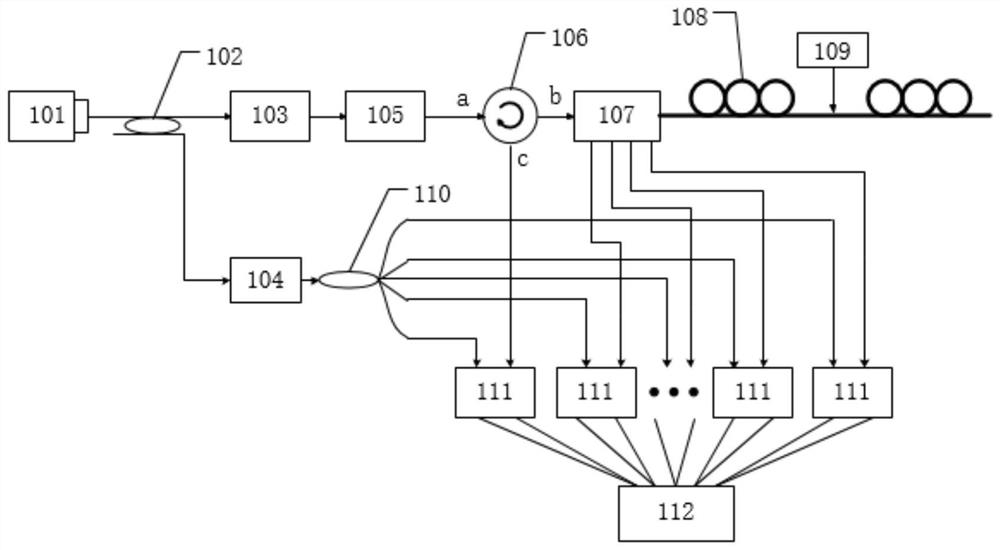
[0107] figure 1 It is a schematic diagram of the overall structure of the acoustic sensor with high signal-to-noise ratio based on the multimode optical fiber of the present invention. Depend on figure 1It can be seen that the multimode optical fiber-based high signal-to-noise ratio acoustic sensor device of the present invention comprises a multimode optical fiber-based high signal-to-noise ratio acoustic sensor. The output port of the laser 101 is connected with the input port of the first fiber coupler 102, the first output port of the first fiber coupler 102 is connected with the optical signal input port of the acousto-optic modulator 103, and the second output port of the first fiber coupler 102 The port is connected to the optical signal input port of the first amplifier 104, the output port of the first amplifier 104 is connected to the input port of the 1×N fiber coupler 110, the optical signal output port of the acousto-optic modulator 103 is connected to the optica...

Embodiment 2

[0111] The detection part of the sensor of the present invention may also include an array detection module, and the schematic diagram of the system structure of this embodiment is as follows Figure 6 shown. The output port of the laser 601 is connected to the input end of the fiber coupler 602, the first output end of the fiber coupler 602 is connected to the optical signal input end of the acousto-optic modulator 603, and the optical signal output port of the acousto-optic modulator 603 is connected to the second amplifier The optical signal input terminal of 604 is connected, and the output port of the second amplifier 604 is connected with a single-mode input port of the device 605 for mode multiplexing, and launches to the device 605 for multiplexing with the base mode LP01 mode , high-order modes in multimode fibers can be excited. The multimode output port of the device 605 for mode multiplexing is connected to the multimode fiber 606, the multimode fiber 606 is conne...

Embodiment 3

[0114] The sensor of the present invention can also use two photon lanterns to multiplex and demultiplex the modes respectively, such as Figure 7 shown. The output port of the laser 701 is connected to the input port of the first fiber coupler 702, the first output port of the first fiber coupler 702 is connected to the optical signal input port of the acousto-optic modulator 703, and the second output port of the first fiber coupler 702 The port is connected to the optical signal input port of the first amplifier 704, the output port of the first amplifier 704 is connected to the input port of the 1×N fiber coupler 712, the optical signal output port of the acousto-optic modulator 703 is connected to the second amplifier 705 The optical signal input terminal is connected, and the output port of the second amplifier 705 is connected with one of the single-mode input ports of the device 706 for mode multiplexing, and the multimode output of the device 706 for mode multiplexing...


PUM


Abstract

The invention discloses a high-signal-to-noise-ratio acoustic sensor based on a multimode optical fiber. The high-signal-to-noise-ratio acoustic sensor comprises a light source part, a modulation part, a mode multiplexing/demultiplexing part, a reference light part, a detection part, a data acquisition part and a sensing part. The light source part, the modulation part, the mode multiplexing/demultiplexing part and the sensing part are sequentially connected, the light source part splits reference light through a first optical fiber coupler of the reference light part, the detection part performs beat frequency on a signal output by the mode multiplexing/demultiplexing part and the reference light, and the output signal is connected to the data acquisition part. According to the invention, a sensing optical fiber is changed from a single-mode optical fiber to a multimode optical fiber, multiple modes in the multimode optical fiber are utilized to sense external sound wave/vibration information, then de-multiplexing is carried out at a detection end or a signal end, and signals detected by N modes are combined, superposed and averaged after diversity, so that the ground noise can be reduced, and the signal-to-noise ratio of the system can be improved; and the sensitivity and the strain resolution of the system are improved.

Description

technical field [0001] The invention relates to the field of acoustic sensors with high signal-to-noise ratio, in particular to an acoustic sensor with high signal-to-noise ratio based on multimode optical fibers. Background technique [0002] Distributed optical fiber acoustic sensing technology uses the phase change of Rayleigh scattered light caused by the acoustic signal acting on the sensing fiber to realize the distributed detection of the acoustic signal. In recent years, with the rapid development of distributed optical fiber sensing technology, optical fiber distributed acoustic detection has also become a hot research direction in the field of optical fiber sensing. As one of the most representative optical fiber distributed acoustic sensing technologies, phase-sensitive optical time domain reflectometer can realize distributed, long-distance and real-time quantitative detection of optical fiber link vibration and acoustic waves. At present, the optical fiber dist...

Claims


Application Information

Patent Timeline
Patent Type & Authority Applications(China)
IPC IPC(8): G01H9/00
CPCG01H9/004Y02D30/70
Inventor 叶青顾金凤卢斌王照勇叶蕾蔡海文
Owner SHANGHAI INST OF OPTICS & FINE MECHANICS CHINESE ACAD OF SCI
Why Eureka
Try Eureka