
Method using ultrasound for the non-destructive examination of a test body

a test body and non-destructive technology, applied in the direction of solid magnetic measurement, and material analysis using sonic/ultrasonic/infrasonic waves. the amount of time and technical equipment required to examine the test body as completely as possible, and the measurement resolution is poor. the effect of reducing the number and thickness, reducing the number of devices, and reducing the number o

Active Publication Date: 2012-02-16
FRAUNHOFER GESELLSCHAFT ZUR FOERDERUNG DER ANGEWANDTEN FORSCHUNG EV
View PDF6 Cites 45 Cited by
  • Summary
  • Abstract
  • Description
  • Claims
  • Application Information

AI Technical Summary

Benefits of technology

[0020]The present invention is an inexpensive method using ultrasound for nondestructive material examination of a test body with which the volume of the test body can be completely examined and the spatial resolution as well as the sensitivity of the measurement are optimized compared to the state of the art. Moreover, the amount of time and technical devices required for material examination are reduced.
[0026]In an advantageous manner, the n ultrasonic transducers are assembled in a manually easy to handle ultrasonic probe permitting simple use and application to the test body surface. Other applications of the ultrasonic transducer, for example to the opposite surfaces of the test body are obtained dependent on the shape and size of the test body and the respective object of examination. It has proven that the method according to the solution permits obtaining optimum spatial resolution of the measurement results if the number of provided ultrasonic transducers selected is at least 16.
[0037]As a result of conducting the preceding process steps, a multiplicity of the m measurement signals stored per measurement period, respectively per measurement cycle, are obtained, which should be analyzed in the following manner based on examination of a test body for a specific purpose. A special aspect is the possibility of evaluating the stored measurement signals later after the actual measurement of the test body. Evaluation of the ultrasonic signals occurs off-line using a reconstruction algorithm, which is selected based on a virtually preset coupling-in angle and / or virtual focussing of the ultrasonic waves coupled into the test body and is applied to the stored ultrasonic signals. With the aid of such reconstruction algorithms, synthetic three-dimensional images of the ultrasonic transmission properties, and reflection properties of the test body can be computed from the stored ultrasonic signals without requiring additional ultrasonic measurements. This reconstruction principle is based on the application of the synthetic aperture focussing technique (SAFT), comprising projecting of all received ultrasonic signals onto a common temporal axis. All of the ultrasonic signals reflected from a certain reflector can be added in phase. Later reconstruction of any coupling-in angle is obtained by a phase-shifted addition of the received signals from different ultrasonic receivers. Off-line evaluation permits synthetic reconstruction of practically any coupling-in angle and in this manner running an ultrasonic “sweep” through the data.
[0038]Compared to the known state of the art, the method of the invention provides a faster, inexpensive method permitting flexible off-line evaluation and assessment of the detected measurement data.
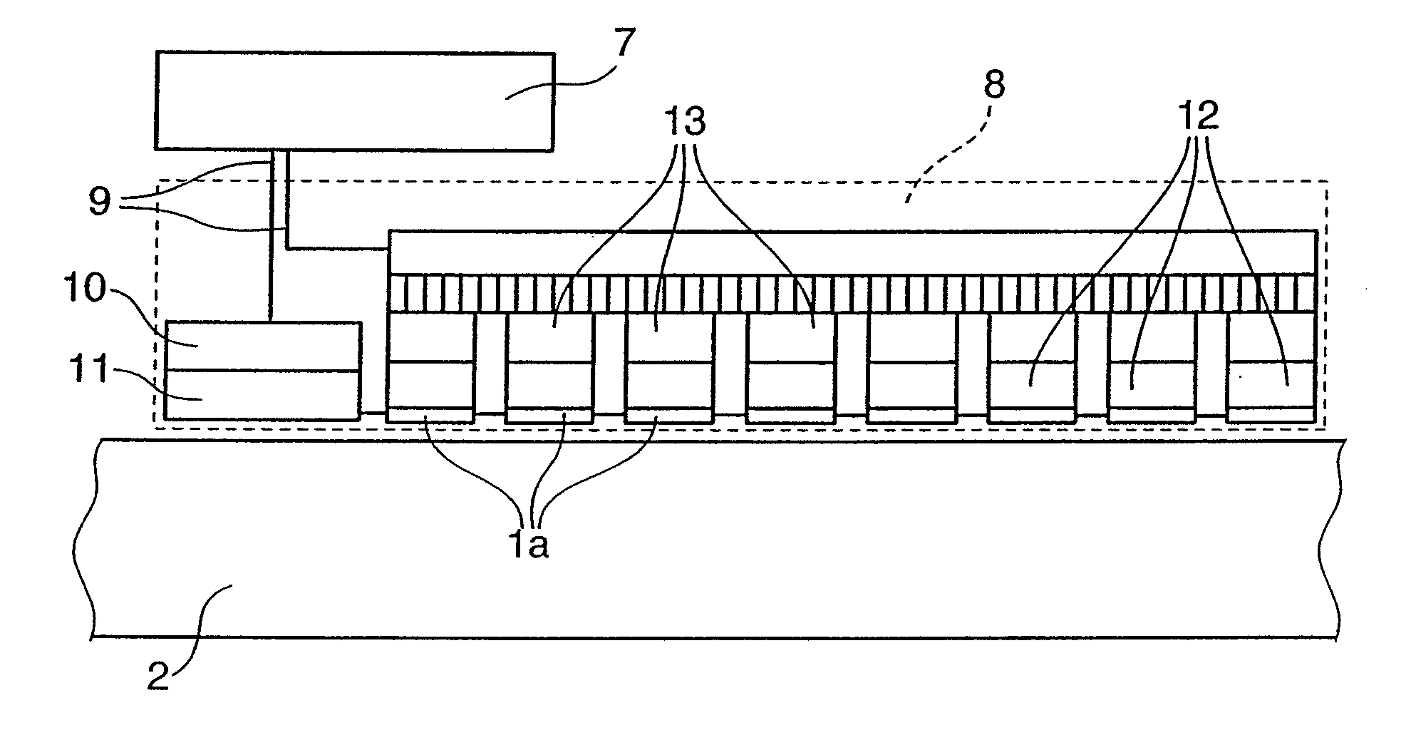
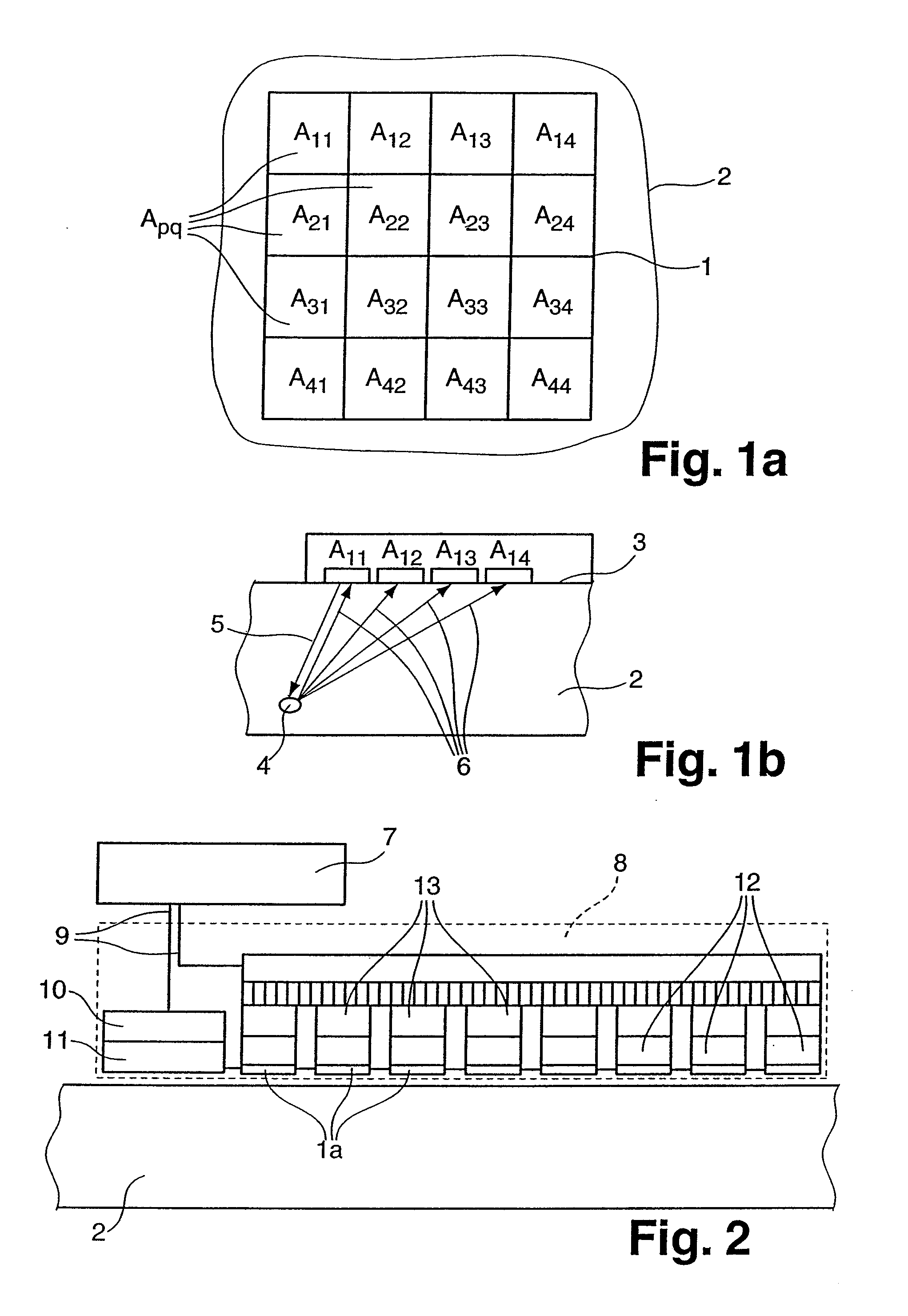
[0040]In another advantageous embodiment, the electrical triggering and activation of all n ultrasonic transducers as digital data occurs between the control unit required for triggering and the ultrasonic transducers. The A / D and D / A converters are provided in the direct vicinity of each ultrasonic transducer. These electronic components can be accommodated directly on the ultrasonic transducers or in a corresponding ultrasonic probe, thereby permitting considerable reduction of the number and thickness of the hitherto used analogue connection cables between the probe and the control unit. Furthermore, in this manner the method is performed with a smaller number and more compact devices.

Problems solved by technology

A drawback in using the phased-array method for non-destructive material examination of a test body, however, is the amount of time and technical equipment required to examine a test body as completely as possible, since the point is to obtain sufficiently reliable measurement signals from all the volume regions for complete signal evaluation.
Examination of the entire test body volume requires a very great number of measurements, each with different phase activation, making the entire material examination very time consuming.
Another disadvantage is that a preset ultrasonic coupling-in angle determines the probe aperture, that is the aperture cannot be optimally selected for all ultrasonic coupling-in angles, yielding poorer measurement resolution.
A further drawback of the phased-array method is that an own transmission channel and a reception channel has to be provided for each ultrasonic transducer with corresponding activation electronics, which has to be connected to the respective ultrasonic transducer via separate electric connections.
As the presently used ultrasonic probes usually comprise 16 or more ultrasonic transducers, connection between the probe and the control device usually requires a thick, inflexible and consequently unwieldy cable.

Method used


Image

  • Method using ultrasound for the non-destructive examination of a test body
  • Method using ultrasound for the non-destructive examination of a test body

Examples


Embodiment Construction

[0045]FIG. 1a shows a top schematical view of a 4×4 transducer array arrangement 1 with sixteen (n=16) ultrasonic transducers Apq. The indices p and q provide the position of the ultrasonic transducer Apq in the array according to row and column. The transducer array 1 is placed on the surface of a test body 2. In this preferred embodiment, the number i of transmitters equals 1 (i=1) and the number m of receivers equals 16 (m=n=16) are selected for all the to-be-conducted measurement periods.

[0046]FIG. 1b shows a cross section of a test body 2 with the cross section area oriented perpendicular to the surface of the test body and through the first row of the ultrasonic transducer array 1 placed on the surface 3. Disposed on surface 3 of the test body 2 are, therefore, the four ultrasonic transducers A11, A12, A13, A14, of array 1 and the other transducers A21-A44. It is assumed that an imperfection 4 is present in the test body 2.

[0047]In a first measurement period, the ultrasonic tr...


PUM


Abstract

The invention relates to a method for the non-destructive examination of a test body by means of ultrasound, whereby ultrasound waves are injected into the test body by means of one or more ultrasound transducers and ultrasound waves reflected inside the test body are received by a plurality of ultrasound transducers and are converted to ultrasound signals. The ultrasound signals are detected in individual measurement intervals and are stored individually and are accessible to offline evaluation after termination of the measurements. The inventive method allows to subsequently synthesize any acoustic irradiation angle and focusing in the physically possible volume range of the test body from the stored ultrasound signals by using corresponding reconstruction algorithms, thereby eliminating the need for additional ultrasound measurements.

Description

BACKGROUND OF THE INVENTION[0001]1. Field of the Invention[0002]The present invention relates to a method using ultrasound for non-destructive examination of a test body, whereby ultrasonic waves are coupled into the test body with one or a multiplicity of ultrasonic transducers and the ultrasonic waves reflected inside the test body are received by a multiplicity of ultrasonic transducers and converted into ultrasonic signals, which form the basis of the non-destructive examination.[0003]2. Description of the Prior Art[0004]The method of using ultrasound for non-destructive examination of a test body, for example for the purpose of examining material for flaws, such as cracks, occlusions or other inhomogeneities, comprises coupling ultrasonic waves into the test body, detection of the ultrasonic waves transmitted or reflected through the test body, deflected, scattered and / or broken in the test body as well as the evaluation of the ultrasonic waves converted into ultrasonic signals...

Claims


Application Information

Patent Timeline
IPC IPC(8): G01N29/04
CPCG01N29/043G01N29/069G01N29/262G01N29/4463G01N2291/044G01N2291/106
Inventor KRONING, MICHAELHENTSCHEL, DIETERVON BERNUS, LUDWIGBULAVINOV, ANDREYREDDY, KRISHNA
Owner FRAUNHOFER GESELLSCHAFT ZUR FOERDERUNG DER ANGEWANDTEN FORSCHUNG EV
Learn More