Spool holder and sewing machine provided therewith

a technology for sewing machines and spools, which is applied in the directions of sewing machine elements, thread break detectors, transportation and packaging, etc., and can solve problems such as unsuitable sewing machine size reduction

Active Publication Date: 2013-06-18
BROTHER KOGYO KK
View PDF35 Cites 2 Cited by
  • Summary
  • Abstract
  • Description
  • Claims
  • Application Information

AI Technical Summary

Benefits of technology

[0009]Therefore, an object of the disclosure is to provide a spool holder which can hold the thread guide member at a predetermined position and can be accommodated in compact, and a sewing machine provided with the spool holder.

Problems solved by technology

However, in the case where the guide position is located high, the thread guide mechanism is bulky upward when the sewing machine is accommodated in the disuse of the sewing machine, thereby being cumbersome.
However, the thread guide mechanism necessitates a space for accommodating the support pillar inside the bracket arm in the sewing machine.
Thus, the first type of thread guide mechanism is subjected to design restrictions at the sewing machine side thereby to be unsuitable for size reduction of the sewing machine.
There is a possibility that the displaced thread guide member may not guide the thread to the thread supply path.

Method used


Image

  • Spool holder and sewing machine provided therewith
  • Spool holder and sewing machine provided therewith
  • Spool holder and sewing machine provided therewith

Examples


first example

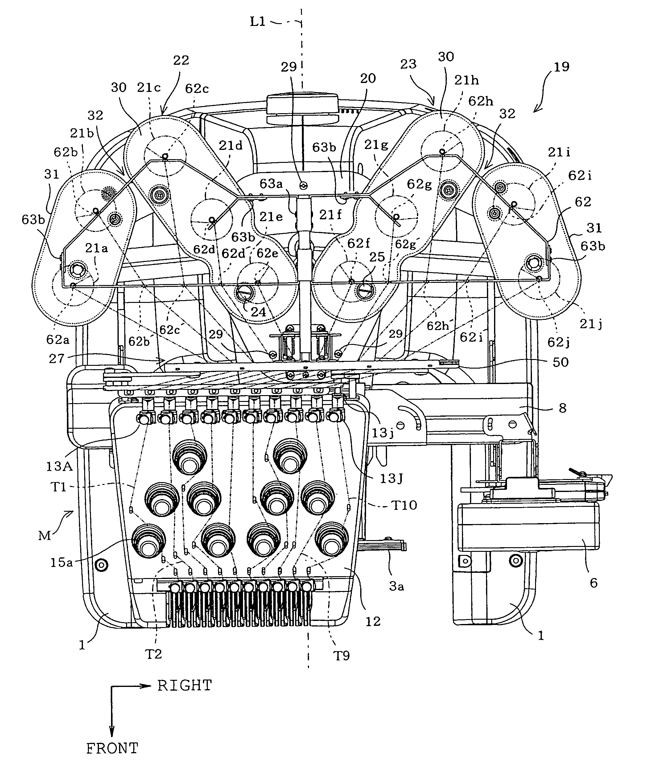
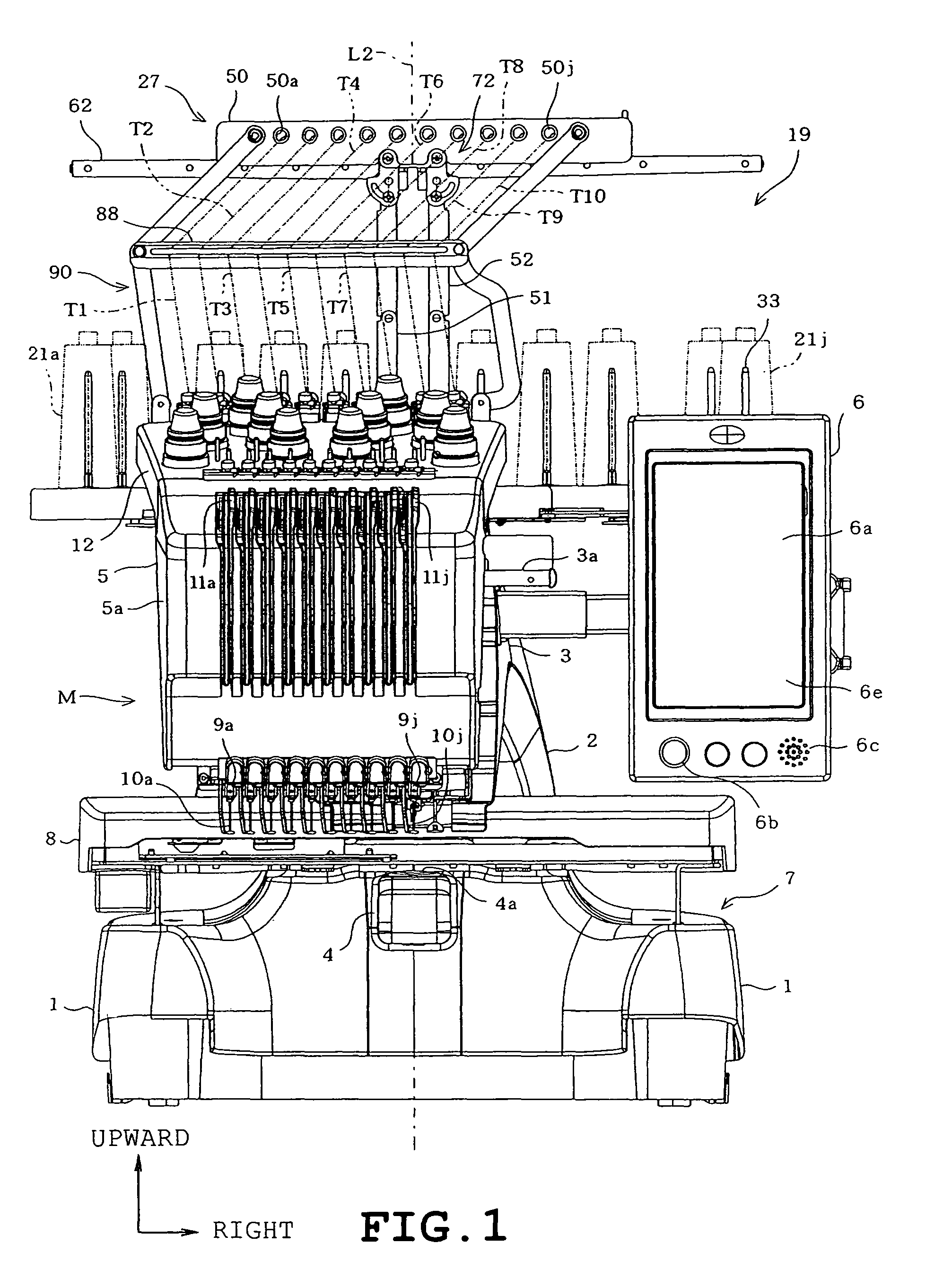
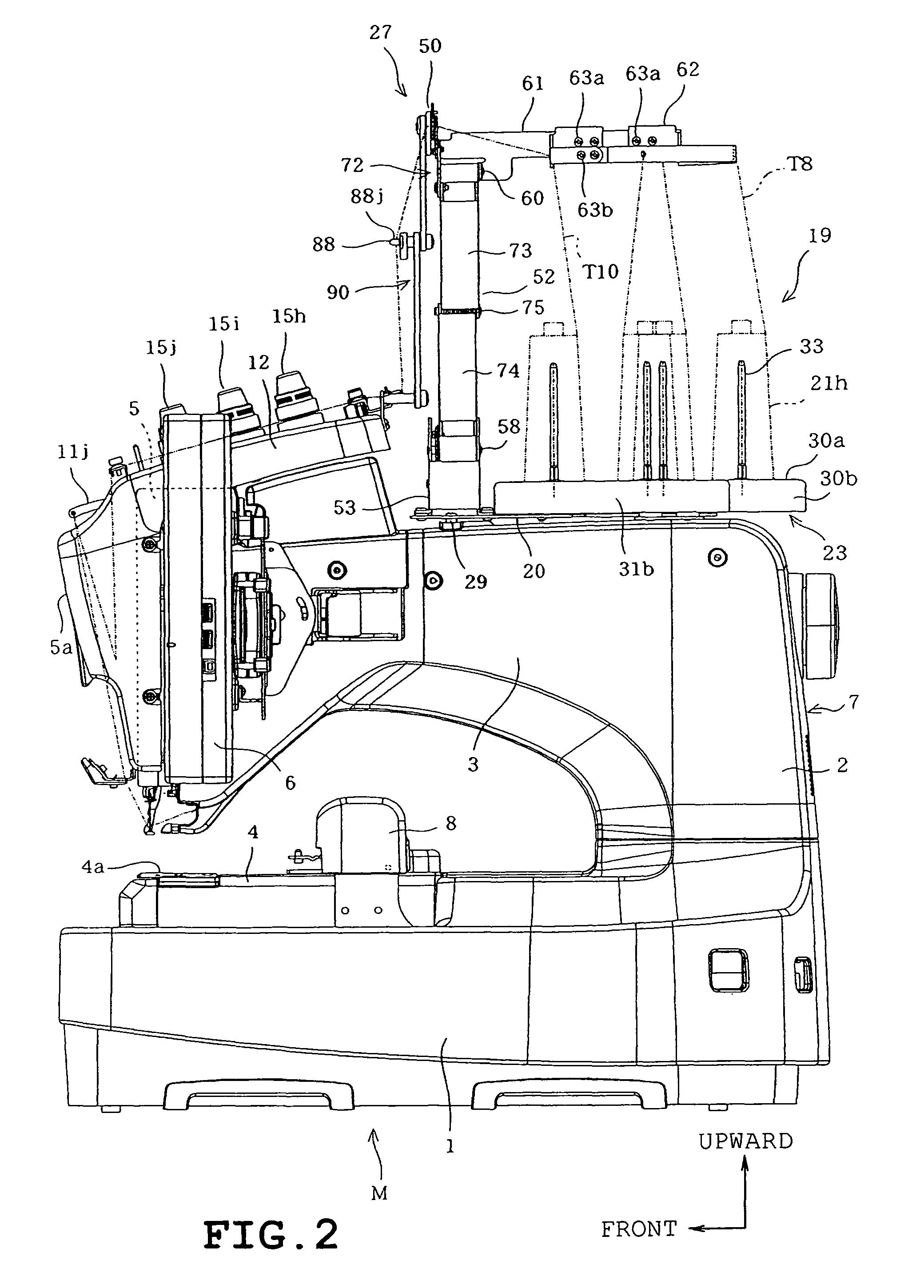
[0028]A first example applied to the multi-needle sewing machine will be described with reference to FIGS. 1 to 15. In the following description, the user is assumed to be located at the front of the multineedle sewing machine M and the opposite side of the sewing machine will be referred to as “the rear.” Furthermore, the front-rear direction will be referred to as “Y direction” and the direction perpendicular to the Y direction will be referred to as “X direction.”

[0029]Referring to FIGS. 1 to 5, the multi-needle sewing machine M includes a pair of right and left legs 1 supporting the overall sewing machine, a pillar 2 standing on rear ends of the legs 1, an arm 3 extending frontward from an upper part of the pillar 2, a cylinder bed 4 extending frontward from a rear end of the pillar 2, and a needle bar case 5 mounted on a front end of the arm 3. The legs 1, pillar 2, arm 3 and cylinder bed 4 are formed integrally with one another into a sewing machine body 7. A control device 18...

second embodiment

[0080]FIGS. 16A and 16B illustrate a second embodiment. Only the difference of the second embodiment from the first embodiment will be described. In FIGS. 16A and 16B, identical or similar parts in the second embodiment are labeled by the same reference symbols as those in the first embodiment.

[0081]The thread guide mechanism 110 in the second embodiment differs from the thread guide mechanism 27 in the first embodiment in the following respects. The thread guide mechanism 110 includes two divided support pillars 51′ and 52. The left divided support pillar 51′ has the upper support pillar 73, the lower support pillar 74, the connecting pin 75 and the torsion coil spring 76 in the same manner as the divided support pillar 51 in the first embodiment. The left divided support pillar 51′ is swingably mounted between the upper and lower pivot pins 59 and 57 while being placed back to front by turning 180 degrees. The locking plate 77′ mounted on the upper part of the left divided support...


PUM


Abstract

A spool holder includes a spool base and a thread guide mechanism including a thread guide member having thread guide portions guiding the threads extending from thread spools, respectively and a divided support pillar disposed so as to support the guide member on the spool base and including an upper support pillar having an upper end swingably mounted on the guide member and a lower support pillar having a lower end which is swingably mounted on the spool base, and a holding unit which holds the divided support pillar so that the pillar is switchable between a first position where both pillars are substantially vertically lined so that the guide member is located at an upper position in its use and a second position where both support pillars are bent at the connecting part so that the guide member is located at an accommodation position in its non-use.

Description

CROSS-REFERENCE TO RELATED APPLICATIONS[0001]This application is based upon and claims the benefit of priority from the prior Japanese Patent Application No. 2009-166770 filed on Jul. 15, 2009, the entire contents of which are incorporated herein by reference.BACKGROUND[0002]1. Technical Field[0003]The present disclosure relates to a spool holder including a spool holder base to which a plurality of thread spools is attachable and a thread guide mechanism which guides, at a location higher than the thread spools, threads extending from the thread spools attached to the spool holder base, and a sewing machine provided with the spool holder.[0004]2. Description of the Related Art[0005]Threads drawn from a plurality of thread spools on a spool holder base respectively are guided by a thread guide mechanism at a location higher than the thread spools in conventional sewing machines provided with the aforementioned spool holder. The threads guided by the thread guide mechanism are passed...

Claims


Application Information

Patent Timeline
Patent Type & Authority Patents(United States)
IPC IPC(8): B65H59/00
CPCD05B43/00
Inventor FUKAO, HIROAKI
Owner BROTHER KOGYO KK
Why Eureka
Try Eureka