Assembly tent

a tent and assembly technology, applied in tents/canopies, constructions, building types, etc., can solve the problems of easy collapse of the tent, easy falling of the traverse beam member, etc., to achieve easy assembly work for the tent, excellent accommodation, and high safety

Active Publication Date: 2015-10-27
NEWTEC JAPAN
View PDF30 Cites 2 Cited by
  • Summary
  • Abstract
  • Description
  • Claims
  • Application Information

AI Technical Summary

Benefits of technology

[0009]A task of the present invention is to provide an assembly tent that is easy to assemble, excellent in strength, and capable of being disassembled and compactly accommodated after use.
[0010]As a result of a study conducted by the inventor in order to solve the task, it has been found that a tent easily assembled and high in strength with respect to a force from the traverse direction can be obtained by inserting, into one member of a traverse beam member and a coupling member, the other member for coupling of the traverse beam member extending horizontally from two adjacent supporting columns at both ends of the coupling member. Thus, the present invention has been completed.
[0019]By inserting the other member into the one member of the traverse beam member and the coupling member in the axial direction, the traverse beam member and the coupling member can be coupled reliably without causing unsteadiness or warpage. Thus, the coupling member does not need to be attached with an auxiliary member such as a supporting column for a solution to the unsteadiness or the like in a coupled portion, and the assembly tent that is lightweight and excellent in accommodability can be provided.
[0020]By inserting the other member into the one member of the traverse beam member and the coupling member in the axial direction, the lock mechanism activates to lock the coupling. Therefore, the safety of the tent is high, and assembly work for the tent can further be performed easily.
[0021]By the traverse beam member and the coupling member being cylinder-shaped and the pin engagement groove for engagement with the lock pin being provided at the circumference of the outer circumference side wall of the member to be inserted, it is possible to lock the coupling merely by inserting the member without considering the directionality. Accordingly, work of inserting while adjusting the direction of the member becomes unnecessary, and assembly work for the tent outdoors can be made easy.
[0022]The tent can be divided into three types of parts of the coupling member, the supporting column provided with the traverse beam member, and a roof structure member for compact accommodation. Upon assembly, the traverse beam member pivoted and spread from the supporting column is coupled at both ends of the coupling member, and the lower end of the spread roof structure is coupled to the supporting column. Accordingly, the framework of the tent can be assembled easily.

Problems solved by technology

However, the truss frame is configured through coupling of an X-shaped frame in which a bar-shaped frame is pivotally attached with a coupling pin to be freely pivotable, and the collapsible tent with this as the traverse beam structure has not necessarily been sufficient in rigidity with respect to stress from the traverse direction.
However, the traverse beam member easily comes off from the socket since the length of the traverse beam member inserted into the socket is short, and unsteadiness or warpage easily occurs in the coupling between the traverse beam member and the coupling member easily.
However, providing such a supporting column to the coupling member not only complicates assembly of the tent, but also increases the volume to be accommodated upon disassembly and folding after use.
Since the weight also increases, carrying around becomes difficult.

Method used


Image

  • Assembly tent
  • Assembly tent
  • Assembly tent

Examples


Embodiment Construction

[0036]An assembly tent according to the present invention will be described below with reference to the drawings.

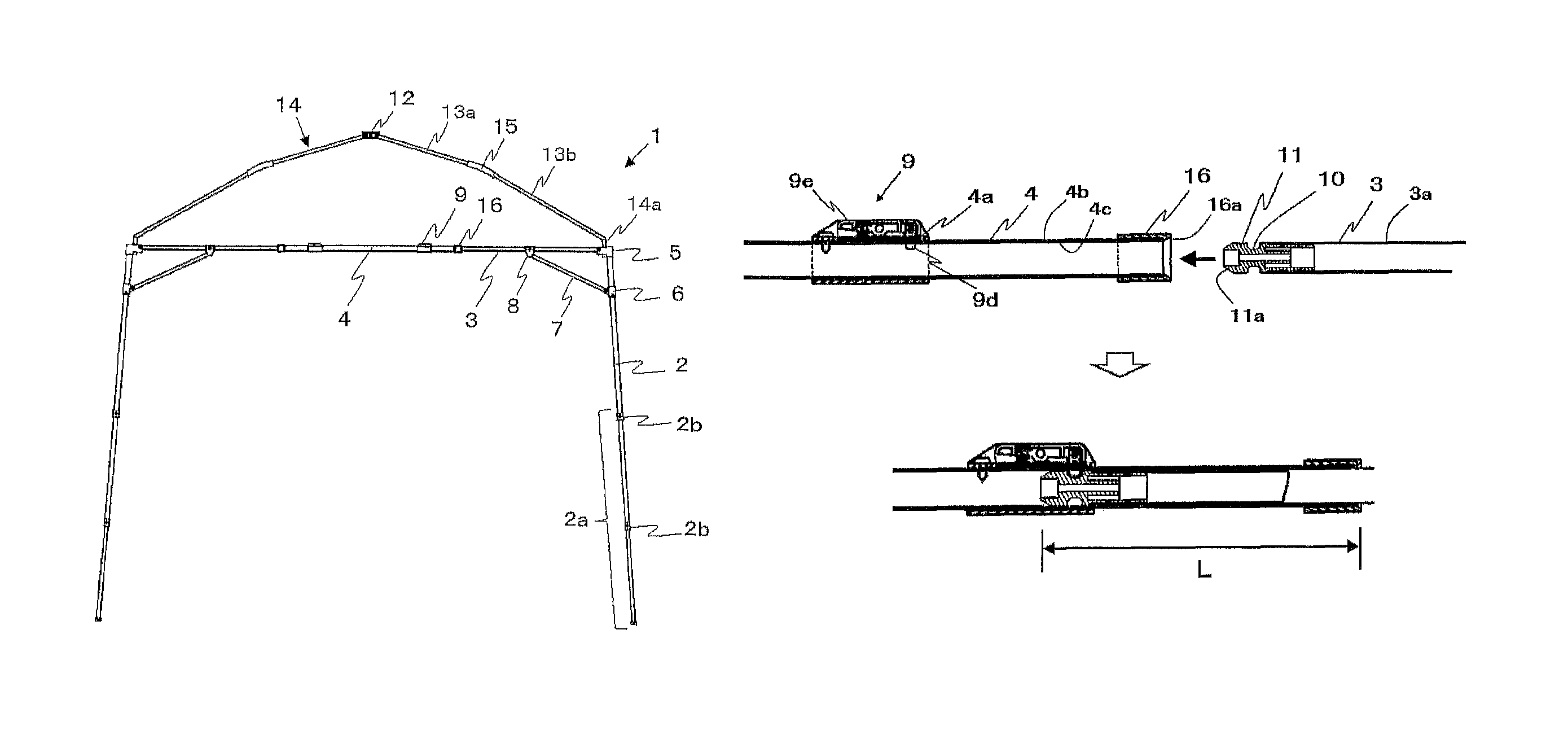
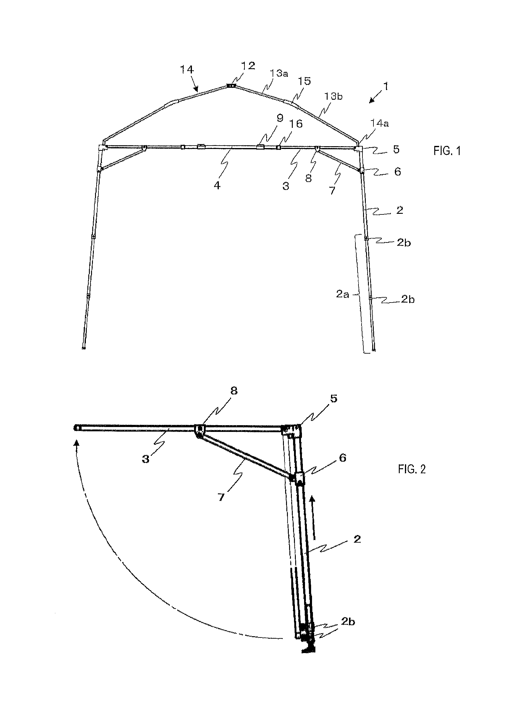
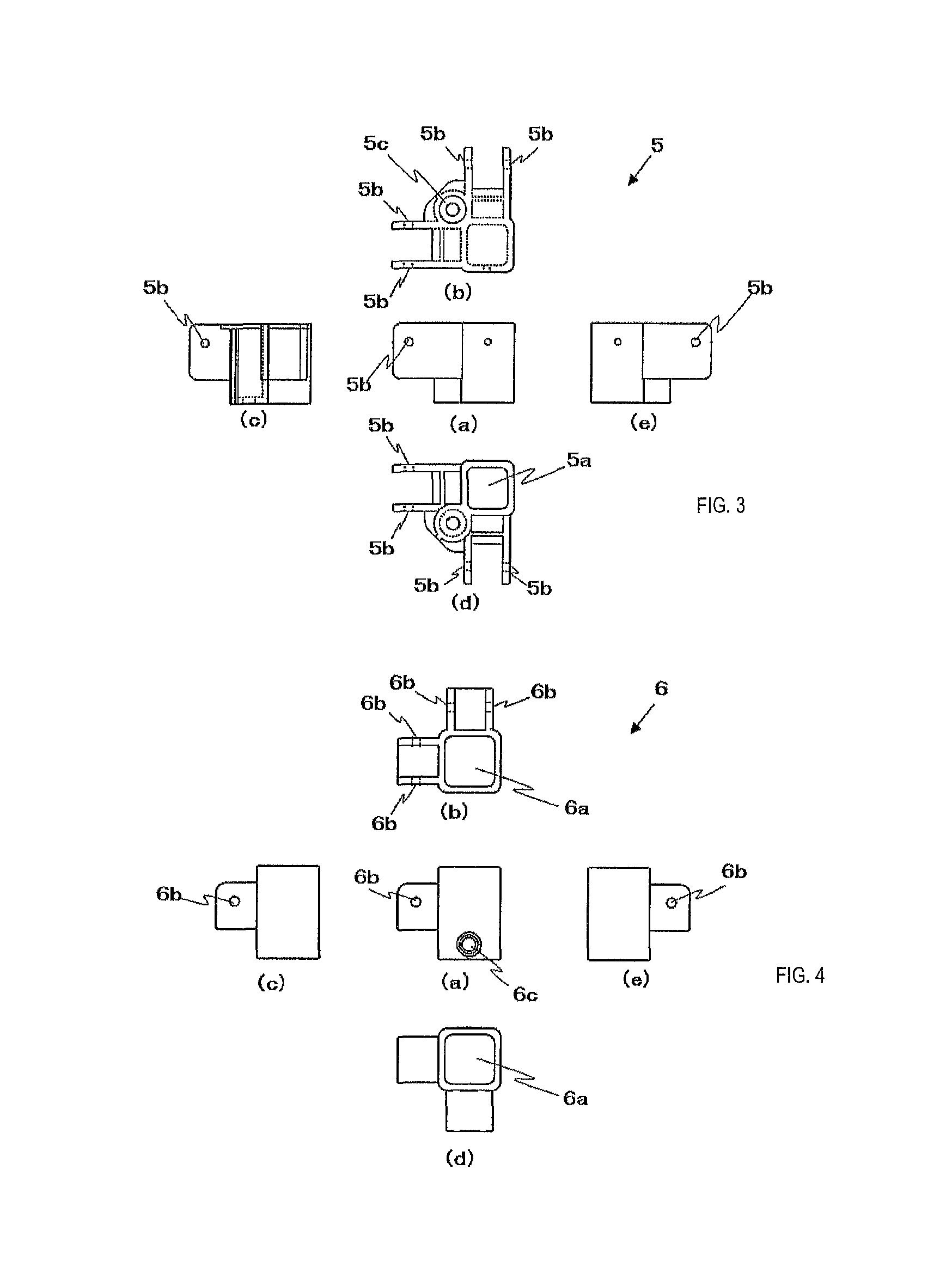
[0037]For the assembly tent, as shown in FIG. 1, a traverse beam member (3) extending horizontally from two adjacent supporting columns (2) is coupled at both ends of a coupling member (4), a plurality of poles (13a) coupled to a top joint (12) are spread, and a lower end portion (coupling portion (14a)) of a roof structure (14) formed through coupling of an extension pole (13b) to each pole (13a) with a pole joint (15) is joined to a fixing bracket (5) at the upper end of the supporting column (2) and coupled with the supporting column (2) to form a framework.

[0038]For the traverse beam member (3), as shown in FIG. 2, the traverse beam member (3) is pivotably attached to the fixing bracket (5) fixed at the upper end of the supporting column (2), and the supporting column and the base end of an auxiliary member (7) are mutually coupled with a slide bracket (6) inserted an...


PUM


Abstract

An object of the present invention is to provide an assembly tent that is easy to assemble, excellent in strength, and capable of being disassembled and compactly accommodated after use. The assembly tent is a tent assembled through coupling of a traverse beam member extending horizontally from two adjacent supporting columns at both ends of a coupling member, wherein coupling between the traverse beam member and the coupling member is formed by inserting, into one member of the traverse beam member and the coupling member, the other member in an axial direction. For establishing the coupling between the traverse beam member and the coupling member, a pin insertion hole is provided to a circumference side wall of the one member of the traverse beam member and the coupling member, a lock mechanism, which biases a lock pin to penetrate the pin insertion hole from an outer circumference side wall and protrude from an inner circumference side wall, is arranged at the outer circumference side wall, and a pin engagement concave portion is arranged at an outer circumference side wall of the other member, such that when the other member is inserted into the one member, the biased lock pin engages with the pin engagement concave portion to lock the coupling between the traverse beam member and the coupling member.

Description

TECHNICAL FIELD[0001]The present invention relates to an assembly tent that is easy to assemble, excellent in strength, and capable of being disassembled and compactly accommodated after use.BACKGROUND ART[0002]A collapsible tent is known in which two adjacent supporting columns are coupled by a truss frame capable of extension and contraction and the supporting columns are pushed and opened to the left and right to spread a traverse beam structure to thereby easily place the tent (Patent Document 1).[0003]However, the truss frame is configured through coupling of an X-shaped frame in which a bar-shaped frame is pivotally attached with a coupling pin to be freely pivotable, and the collapsible tent with this as the traverse beam structure has not necessarily been sufficient in rigidity with respect to stress from the traverse direction.[0004]There is a conventional assembly tent that is assembled through coupling of a traverse beam member extending horizontally from two adjacent sup...

Claims


Application Information

Patent Timeline
Patent Type & Authority Patents(United States)
IPC IPC(8): E04H15/34E04H15/48
CPCE04H15/34E04H15/48E04H15/44
Inventor SHIRAISHI, TOKUHIRO
Owner NEWTEC JAPAN
Why Eureka
Try Eureka