Valve Gear

a valve gear and gear technology, applied in the direction of valve arrangement, machines/engines, mechanical equipment, etc., can solve the problems of increasing the variation of lift characteristics, increasing the number of parts, and increasing the number of valves, so as to achieve the adjustment of the lift variation for each valv

Active Publication Date: 2013-11-14
KAWASAKI MOTORS LTD
View PDF1 Cites 2 Cited by
  • Summary
  • Abstract
  • Description
  • Claims
  • Application Information

AI Technical Summary

Benefits of technology

[0030]As described above, according to the valve gear of the present invention, at least one of the intake-side and exhaust-side valve gears is unitized as a unit so as to be compactly accommodated in the case member, and then this unit is removably installed in the cylinder head. Accordingly, installation of the unit to the cylinder head is facilitated and adjustment of the lift variation for each valve may be easily performed before the installation. Furthermore, it is easy to secure the rigidity of the case member of the valve gear unit, and a practical effect of adjusting the lift variation before installing the valve gear unit in the cylinder head can be obtained.

Problems solved by technology

In the case of incorporating such a variable mechanism, the structure of the valve operating system becomes complicated, leading to an increased number of parts.
Accordingly, if the number of the component parts of the valve operating system increases like the above-mentioned conventional art, those variations may be superimposed, so that an increase in variations in lift characteristics, such as a lift amount, lift timing, and the like of valves may not be avoidable.

Method used


Image

  • Valve Gear
  • Valve Gear
  • Valve Gear

Examples


Embodiment Construction

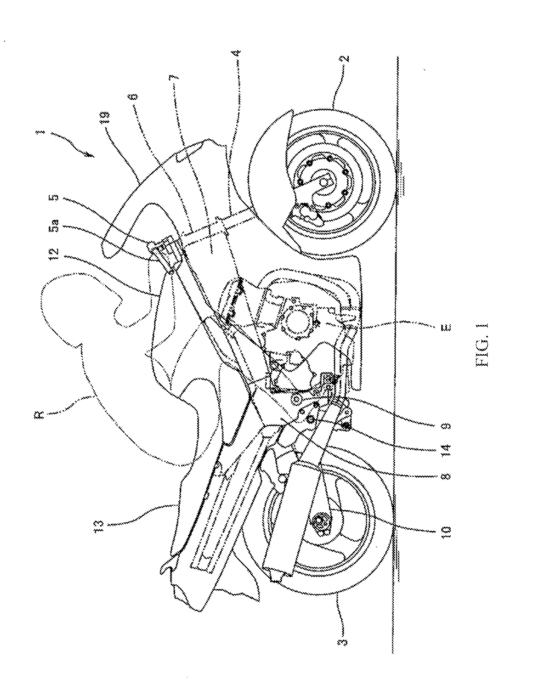
[0041]Hereinafter, an embodiment of a valve gear according to the present invention will be described with reference to the drawings. FIG. 1 is a right side view of a motorcycle 1 to which an engine E according to an embodiment of the present invention is mounted. As for directions in the following embodiments, directions are referenced from a perspective of a rider R mounting the motorcycle 1.

[0042]As illustrated in FIG. 1, the motorcycle 1 includes a front wheel 2 as a steering wheel and a rear wheel 3 as a driving wheel. The front wheel 2 is rotatably supported by lower ends of a pair of left and right front forks 4 which almost vertically extend. On the other hand, upper portions of the front forks 4 are supported by a steering shaft (not illustrated) via a pair of brackets, an upper bracket and a lower bracket. A bar-like handle 5 which extends rightward and leftward is attached to the upper bracket, and a steering shaft is supported so as to be rotatable in a state where it is...


PUM


Abstract

A valve gear operates an intake valve for a plurality of cylinders. The valve gear includes a driving cam shaft that rotates with an engine crankshaft, a driven member operated by a driving cam of the driving cam shaft, a pivot member which pivots in association with movement of the driven member causing the intake valve to reciprocate, and a valve gear case accommodating the cam shaft, the driven member, the pivot member, and a control shaft. The valve gear case mounts to an intake-side part of a cylinder head, and includes end wall portions at both ends in a longitudinal direction, an inter-cylinder wall portion, and connection wall portions connecting the end wall portions and the inter-cylinder wall portion.

Description

TECHNICAL FIELD[0001]The present invention relates to a valve gear of an engine, and more particularly to the structure of a valve gear provided in a cylinder head for operating an intake valve or an exhaust valve.BACKGROUND ART[0002]Generally a so-called double overhead cam shaft-type (DOHC type) valve operating system which has a pair of cam shafts for operating an intake valve and an exhaust valve, individually is conventionally adopted in a high-performance engine. In this structure, intake-side and exhaust-side cam shafts are arranged side by side on a cylinder head in a manner of rotating in synchronization with rotation of a crankshaft (an output shaft of an engine), and the intake valve and exhaust valve for each cylinder are made to reciprocate by a driving cam of each cam shaft. A pivot mechanism, such as a rocker arm, may be interposed between the driving cam and the valve.[0003]In recent years, among the pivot mechanisms, a pivot mechanism including a so-called lost moti...

Claims


Application Information

Patent Timeline
Patent Type & Authority Applications(United States)
IPC IPC(8): F01L1/047F01L1/18
CPCF01L1/047F01L1/18F01L1/053F01L13/0026F01L2001/0537F01L1/022
Inventor ICHI, SATOAKI
Owner KAWASAKI MOTORS LTD
Why Eureka
Try Eureka